Sensor, Measuring Device, And Measuring Method

a technology of measuring device and sensor, applied in the field of measuring device and measuring method, can solve the problems of reducing medical expenses, straining medical economy, and less applicable all-purpose use of the poct device compared to the large-scale automated device, and achieves the effects of simple structure, fast and accurate measurement, and reduced medical expenses

Active Publication Date: 2008-05-08
PANASONIC CORP
View PDF9 Cites 8 Cited by
  • Summary
  • Abstract
  • Description
  • Claims
  • Application Information

AI Technical Summary

Benefits of technology

[0046]Based on the present invention, with a sensor having a simple structure as noted in the above, an optical measurement and an electrochemical measurement of a sample can be done simultaneously, and a plurality of items can be measured quickly and accurately. Especially, although there is a problem in that usually a reagent used for the optical measurement gives adverse effects on an electrochemical measurement, based on the above structure, such problem can be solved. Further, based on the present invention, with the use of the sensor, a measuring device and a measuring method in which a plurality of items can be measured quickly and accurately can be realized.

Problems solved by technology

These POCT devices are less applicable for all-purpose use compared with large-scale automated devices, but capable of easy and quick measurement by focusing on a marker substance unique to a disease.
Recently, a rise in medical expense and an increase in lifestyle-related disease patient have been causing a strain on medical economy, and a reduction in medical expense and avoidance on increase in lifestyle-related disease patient have been problems.
However, the complicated structure of the device makes the operation difficult for those without expertise, and further, there are problems in that it takes long to obtain test results, and involves a longer time for giving the feedback of the results to the examinee.
Additionally, although the above POCT device is excellently operable and is capable of easy and quick test, it is a measuring device specially for a marker related to a specific disease, and is not capable of testing a plurality of items.

Method used


Image

  • Sensor, Measuring Device, And Measuring Method
  • Sensor, Measuring Device, And Measuring Method
  • Sensor, Measuring Device, And Measuring Method

Examples


embodiment 1

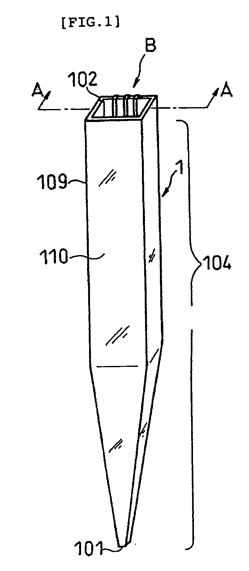
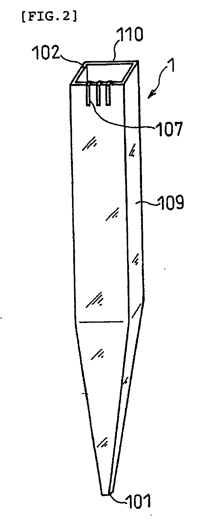
[0144]A structure of a sensor in this embodiment is described by using FIGS. 1 to 3. The sensor in this embodiment is structured with an intension of using a scattered light for the optical measurement. FIG. 1 is a perspective view showing Embodiment 1 of the sensor of the present invention. FIG. 2 is a perspective view of the sensor seen from the direction of arrow B in FIG. 1. FIG. 3 is a cross section at lines A-A in FIG. 1.

[0145]As shown in FIG. 1, a sensor 1 in this embodiment is formed with a sample-holding unit 104 formed of polystyrene.

[0146]The sample-holding unit 104 has a form of a combination of a hollow quadrangular pyramid and a hollow quadrangular prism with square cross sections, and at a tip of the quadrangular pyramid, a sample-supplying port 101 is provided. Also, on the opposite side of the sample-supplying port 101, an opening 102 is provided. Then, the sensor in this embodiment is structured so that a sample is supplied from the sample-supplying port 101 to the...

embodiment 2

[0154]A structure of a sensor in this embodiment is described by using FIGS. 4 to 6. The sensor in this embodiment is structured with an intension of using a transmitted light for the optical measurement. FIG. 4 is a perspective view showing Embodiment 2 of the sensor of the present invention. FIG. 5 is a perspective view of the sensor seen from the direction of arrow B in FIG. 4. FIG. 6 is a cross section at lines A-A in FIG. 4.

[0155]As shown in FIG. 4, a sensor 1 in this embodiment is formed with a sample introducing unit 203 formed of polystyrene, and a sample-holding unit 204. The sample introducing unit 203 and the sample-holding unit 204 are formed integrally.

[0156]The sample introducing unit 203 has a cylindrical form, with a sample-supplying port 201 provided on a tip thereof. Also, the sample-holding unit 204 has a form of a hollow quadrangular prism with square cross sections, and on the opposite side of the sample-supplying port 201, an opening 202 is provided. Then, the ...

embodiment 3

[0164]A structure of a sensor in this embodiment is described by using FIGS. 7 to 9. The sensor in this embodiment is structured with an intension of using a scattered light for the optical measurement. FIG. 7 is a perspective view showing Embodiment 3 of the sensor of the present invention. FIG. 8 is a perspective view of the sensor seen from the direction of arrow B in FIG. 7. FIG. 9 is a cross section at lines A-A in FIG. 7.

[0165]As shown in FIG. 7, a sensor 1 in this embodiment is formed with a sample introducing unit 303 formed of polystyrene and a sample-holding unit 304. And the sample introducing unit 303 and the sample-holding unit 304 are integrally formed.

[0166]The sample introducing unit 303 has a cylindrical form, with a sample-supplying port 301 provided on a tip thereof. Also, the sample-holding unit 304 has a form of a bottomed hollow quadrangular prism with square cross sections, and at a lower portion of a first face among the four faces, a sample-introducing path ...


PUM

PropertyMeasurementUnit
concentrationaaaaaaaaaa
temperatureaaaaaaaaaa
concentrationaaaaaaaaaa

Abstract

A sensor capable of measuring a plurality of measuring items quickly and accurately, a measuring device, and a measuring method are provided. The sensor includes a sample-holding unit for holding a sample containing an analyte; a sample-supplying port for supplying the sample to the sample-holding unit; a detecting unit for carrying out an electrochemical measurement, the unit being provided in the sample-holding unit; an optical measuring unit for carrying out an optical measurement, the unit being provided in the sample-holding unit; and a reagent-holding unit for holding a reagent for the optical measurement, the unit being provided in the sample-holding unit; wherein in the flowing direction of the sample supplied from the sample-supplying port in sample-holding unit, the sample-supplying port, the detecting unit, and the reagent-holding unit are positioned in the order recited.

Description

TECHNICAL FIELD[0001]The present invention relates to sensors for measuring a plurality of items of a sample, and to a measuring device and a measuring method using the sensor.BACKGROUND ART[0002]Measuring devices that are conventionally used in the field of clinical testing are mainly large-scale automated devices and POCT (Point of Care Testing) devices.[0003]The large-scale automated devices are provided at a central clinical-testing department of hospitals and at companies that mainly undertake clinical testings, and by using these devices, a sample of many patients can be tested for a plurality of items (for example, Patent Publication Document 1). For example, a large automated device manufactured by Hitachi, Ltd., type 7170, is capable of completing 800 tests / hour on 36 items at maximum. Therefore, the large-scale automated device has been contributing to efficiency in testing, which makes it suitable for hospitals with a large number of examinee.[0004]On the other hand, POCT...

Claims


Application Information

Patent Timeline
Patent Type & Authority Applications(United States)
IPC IPC(8): G01N27/27G01N27/28G01N21/59G01N21/64G01N27/26G01N27/327G01N27/333G01N27/416G01N27/49G01N33/483G01N33/487G01N33/493G01N33/53G01N33/84
CPCG01N21/03G01N33/5302G01N33/48707G01N21/59
Inventor KITAWAKI, FUMIHISAKAMEI, AKIHITOKAWAMURA, TATSUROU
Owner PANASONIC CORP
Why Eureka
Try Eureka