Connector assembly with gripping sleeve

a technology of connector assembly and sleeve, which is applied in the direction of coupling device connection, coupling device details, coupling/disassembly parts, etc. it can solve the problems of signal leakage, loose connection can come apart, and loose connection can not provide continuity, so as to facilitate gripping and mating of the connector

Active Publication Date: 2008-12-25
AMPHENOL CORP
View PDF65 Cites 17 Cited by
  • Summary
  • Abstract
  • Description
  • Claims
  • Application Information

AI Technical Summary

Benefits of technology

[0006]Accordingly, it is an aspect of the invention to provide a connector assembly with a connector and a sleeve to facilitate gripping and mating of the connector to its counterpart connector.

Problems solved by technology

A loose connection can fail to provide the positive contact needed for continuity between the cable and the device, the other connector, or the other cable.
Also, a loose connection can come apart accidentally disrupting the connection to the device, the other connector, or the other cable.
A loose connection can also cause signal leakage and degraded performance.
Furthermore, connector assemblies are often assembled under conditions in which the user cannot adequately grasp the nut portion of the connector assembly.
Without a sure grip, the user often fails to properly mate the connector assembly with the other device, the other connector, or the other cable.
Also, the likelihood of a loose connection occurring increases, making the connector assembly more susceptible to separating from the device, the other connector, or the other cable and may cause signal leakage.

Method used


Image

  • Connector assembly with gripping sleeve
  • Connector assembly with gripping sleeve
  • Connector assembly with gripping sleeve

Examples


Embodiment Construction

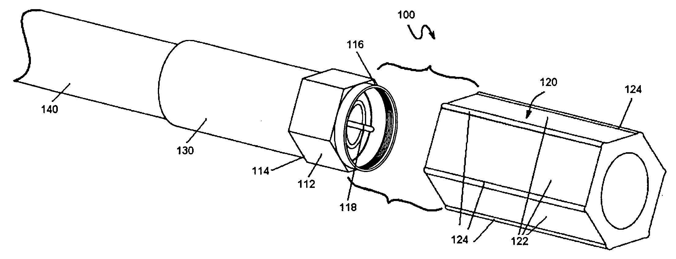
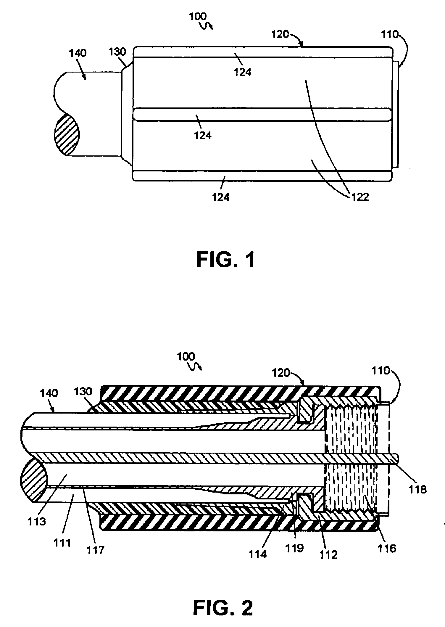
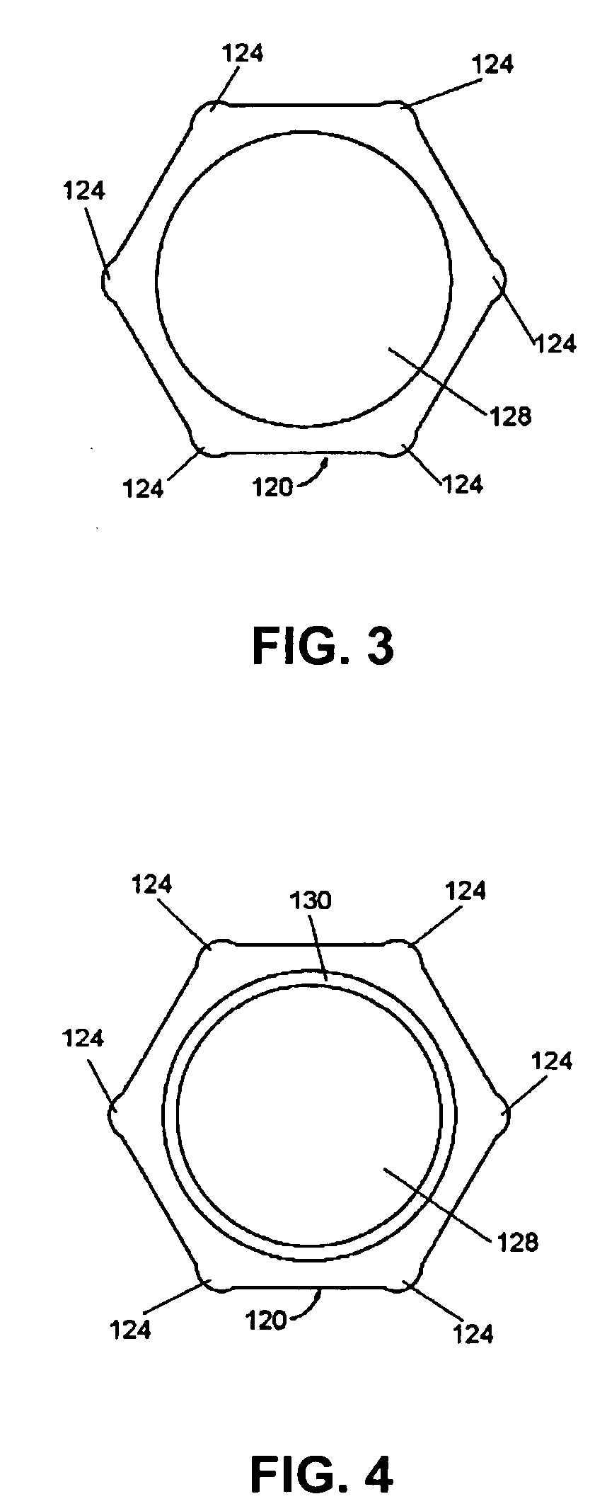
[0021]Referring to FIGS. 1-9 the present invention relates to a connector assembly 100 with a sleeve 120 that is fixed to a connector 110. The sleeve 120 provides improved gripping of the connector 110. The sleeve 120 does not come off of the connector assembly 100 for safety reasons.

[0022]Referring to FIG. 1, the connector assembly 100 includes, at least, the connector 110 and the sleeve 120. The connector assembly 100 may also include a tube 130. If the connector assembly 100 includes the tube 130, then the sleeve 120 is disposed over the tube 130 and the connector 110.

[0023]The connector 110 is configured to terminate a cable 140 and adapt the cable 140 for attachment to a device, another connector, or another cable. The connector 110 can be an electrical connector, an optical connector, a fluid connector, a pneumatic connector, a hydraulic connector, or some other type of connector. To simplify and facilitate the description of the invention, the connector 110 will be described ...


PUM


Abstract

A connector assembly includes an electrical connector and a sleeve. The electrical connector has opposite first and second ends. The first end is rotatable with respect to the second end and configured to couple to a mating connector. The second end is configured to terminate a cable. The sleeve is molded over the first end such that the sleeve is fixed to the first end, and the sleeve and the first end of the connector together rotate with respect to the second end of the connector. Also, the sleeve has an outer gripping surface.

Description

CROSS-REFERENCE TO RELATED APPLICATION [0001]This application claims priority under 35 U.S.C. §119(e) to U.S. Provisional Patent Application No. 60 / 929,266, entitled “Connector Assembly with Gripping Sleeve” by Richard Paglia et al., filed on Jun. 20, 2007, the entire disclosure of which is incorporated herein by reference.FIELD OF THE INVENTION [0002]The present invention relates to connector assemblies with a sleeve. In particular, the present invention relates to electrical connector assemblies with an overmolded sleeve to facilitate gripping and mating of the connector to its counterpart connector.BACKGROUND OF THE INVENTION[0003]Connector assemblies are often used to terminate a cable and adapt the cable for attachment to a device, another connector, or another cable. The connector assembly often includes a body with a rotating nut portion with internal threads. The nut portion rotates with respect to the body so that the internal threads of the nut can engage corresponding thr...

Claims


Application Information

Patent Timeline
Patent Type & Authority Applications(United States)
IPC IPC(8): H01R9/05
CPCH01R9/0518H01R43/24
Inventor PAGLIA, RICHARDCHEN, WEIXINGGU, MINGHUA
Owner AMPHENOL CORP
Why Eureka
Try Eureka