Retaining ring removal tool

a technology of retaining rings and retaining rings, which is applied in the direction of metal-working hand tools, manufacturing tools, etc., can solve the problems of inefficiency or effectiveness, relative difficulty in removing or putting in position on the rod or pin, and conventional tools such as needle nose pliers, while they can be used, and achieves minimal handling, simple but effective

Inactive Publication Date: 2009-01-01
BLOK STEPHEN
View PDF4 Cites 6 Cited by
  • Summary
  • Abstract
  • Description
  • Claims
  • Application Information

AI Technical Summary

Benefits of technology

[0008]It will be immediately appreciated that a simple but effective tool is provided that will easily permit removal of rods from ring clips (or insertion of rods into ring clips) with a minimum of handling of the ring clip by tools or one's fingers.

Problems solved by technology

Because such clips are relatively small in size, and are under considerable tension when in position on the rod or pin, they are relatively difficult to remove or to insert in position on the rod or pin.
Conventional tools, such as needle nose pliers, and screwdrivers, while they can be used, are not efficient or effective.

Method used


Image

  • Retaining ring removal tool
  • Retaining ring removal tool
  • Retaining ring removal tool

Examples


Embodiment Construction

[0019]In the following description, similar features in the drawings have been given identical reference numerals where appropriate. All dimensions described or suggested herein are intended solely to illustrate an embodiment. These dimensions are not intended to limit the scope of the invention that may depart from these dimensions.

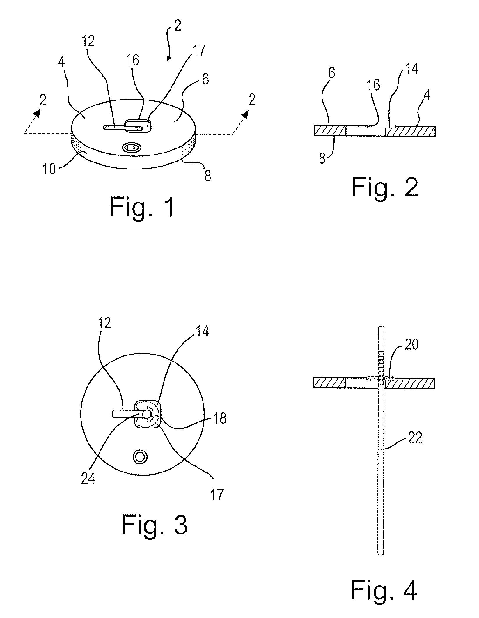
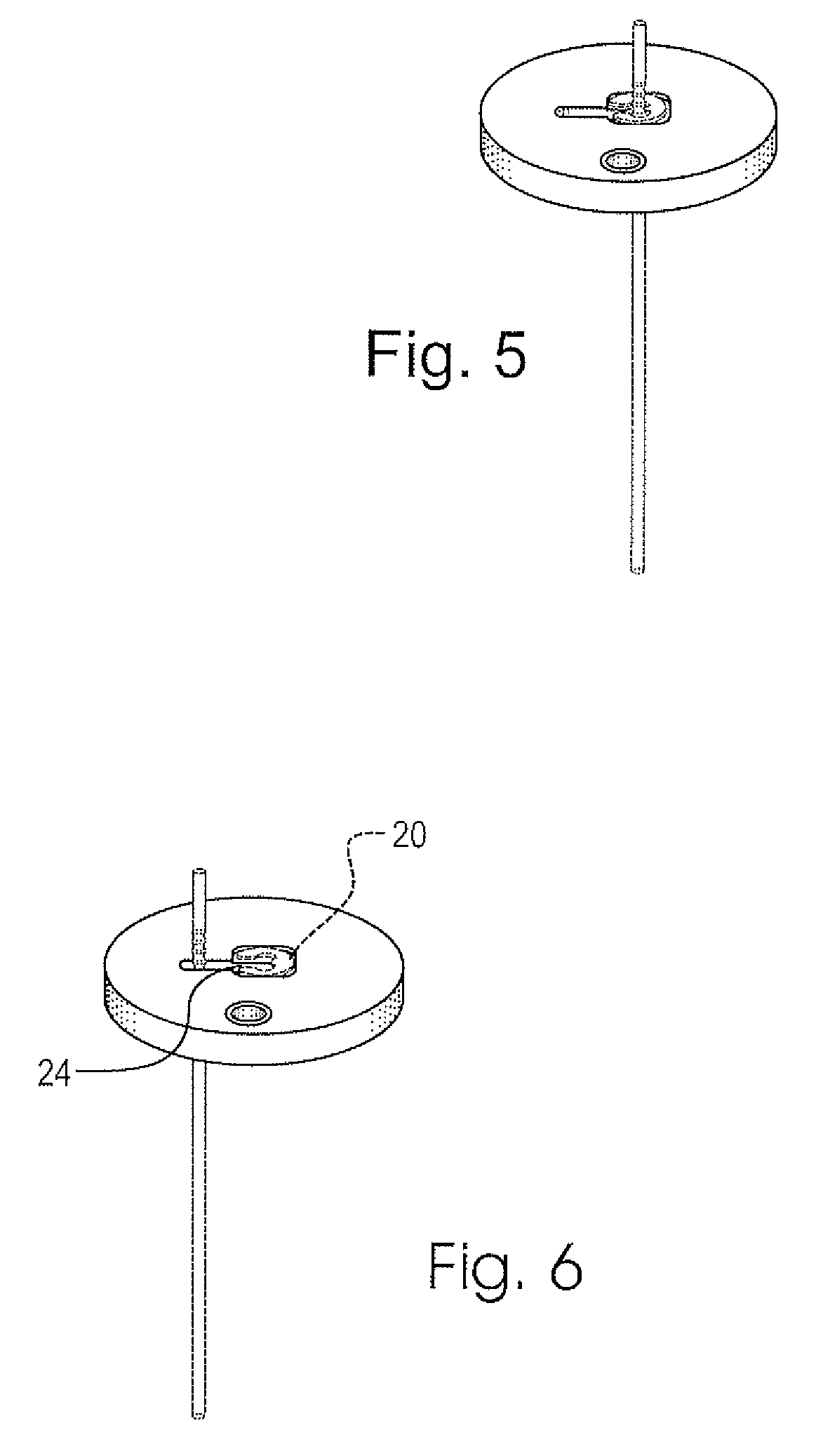
[0020]Turning to the embodiment of tool illustrated in FIGS. 1 to 6, there is illustrated a tool 2 for removal and insertion of rods with respect to ring clips comprising a body 4 having opposed flat parallel upper surface 6 and lower surface 8, and a circumscribing, circular peripheral edge 10. A linear, rod receiving aperture 12 extends through body 2, from surface to surface, the aperture disposed from a central portion of body 2, radially outwardly towards edge 10. A ring clip receiving depression 14 is provided in upper surface 6 as illustrated, the depression having walls 16 and a base 17 configured to seat a spring clip 20 in a manner which will b...


PUM

PropertyMeasurementUnit
sizeaaaaaaaaaa
heightaaaaaaaaaa
thicknessaaaaaaaaaa

Abstract

A tool for removal of a rod from an opening in a ring clip or for insertion of the rod through the opening into the ring clip. The tool comprises a body having an upper surface, a ring clip receiving depression in that surface and an aperture in that surface extending below the depression and to one side thereof. The aperture is of a size to receive at least a portion of the rod to which is, or is to be, attached while the ring clip is seated within the depression. The depression has a base and walls which are configured so as to seat a ring clip therein to restrain it against relative movement in a direction towards the opening of the ring clip when the rod is moved in that direction for removal from the ring clip through the opening, and to restrain it against relative movement in an opposite direction when the rod is moved in that opposite direction to be inserted into the ring clip through the opening.

Description

FIELD OF THE INVENTION[0001]The present invention relates to a tool to facilitate removal of pins, needles and rods from ring clips, such as e-clips.BACKGROUND OF THE INVENTION[0002]Ring clips, such as e-clips, are very commonly used today. For instance e-clips are releasably positioned in one of a series of adjacent grooves in jet needles in internal combustion engine carburetors, to permit positioning of that needle to adjust fuel flow to the carburetor.[0003]Because such clips are relatively small in size, and are under considerable tension when in position on the rod or pin, they are relatively difficult to remove or to insert in position on the rod or pin. Conventional tools, such as needle nose pliers, and screwdrivers, while they can be used, are not efficient or effective. Indeed, instructions for removing an e-clip from a needle often recommend that the safest way to remove the clip is to work in a clean uncluttered area so that if and when the clip flies into space, the me...

Claims


Application Information

Patent Timeline
Patent Type & Authority Applications(United States)
IPC IPC(8): B25B27/00
CPCY10T29/53909B25B27/20
Inventor BLOK, STEPHEN
Owner BLOK STEPHEN
Why Eureka
Try Eureka