

Rotating electrical machine
a technology of rotating electrical machines and rotating shafts, which is applied in the direction of dynamo-electric machines, magnetic circuit shapes/forms/construction, supports/enclosements/casings, etc., can solve the problem that the statator coil assuming a complex structure cannot be manufactured with a high level of productivity, and achieve the effect of improving productivity and efficiency
- Summary
- Abstract
- Description
- Claims
- Application Information
AI Technical Summary
Benefits of technology
Problems solved by technology
Method used
Image

Examples
first embodiment
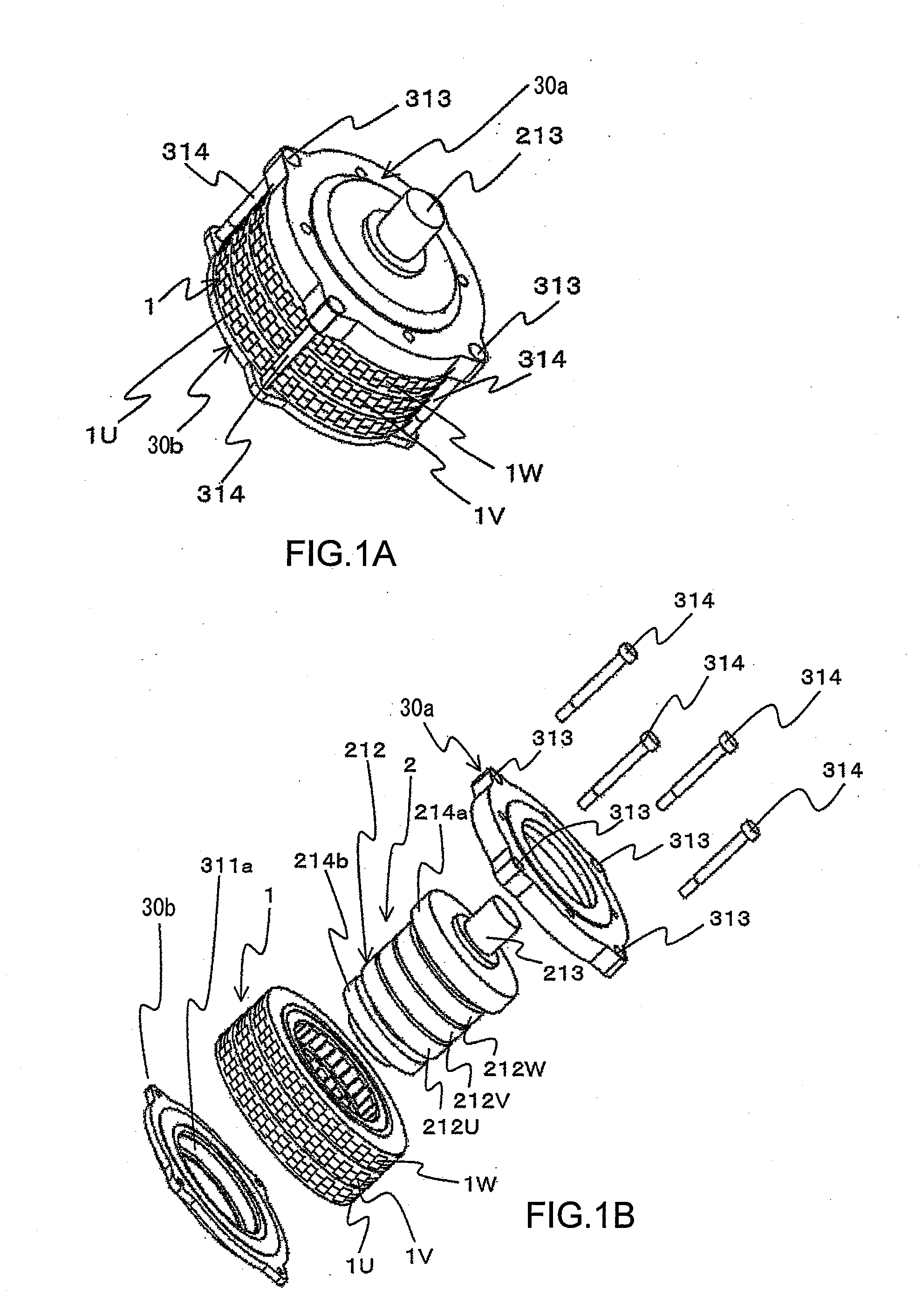
[0207]In reference to FIGS. 1A through 9D, a rotating electrical machine in the first embodiment according to the present invention is described. The rotating electrical machine in the embodiment is a motor that outputs a rotational force as an electric current is supplied thereto, utilized in industrial applications, home appliance applications, OA equipment applications, automotive applications and the like. The advantages of the present invention become particularly obvious when the present invention is adopted in a relatively large rotating electrical machine such as an automotive generator or an automotive motor.
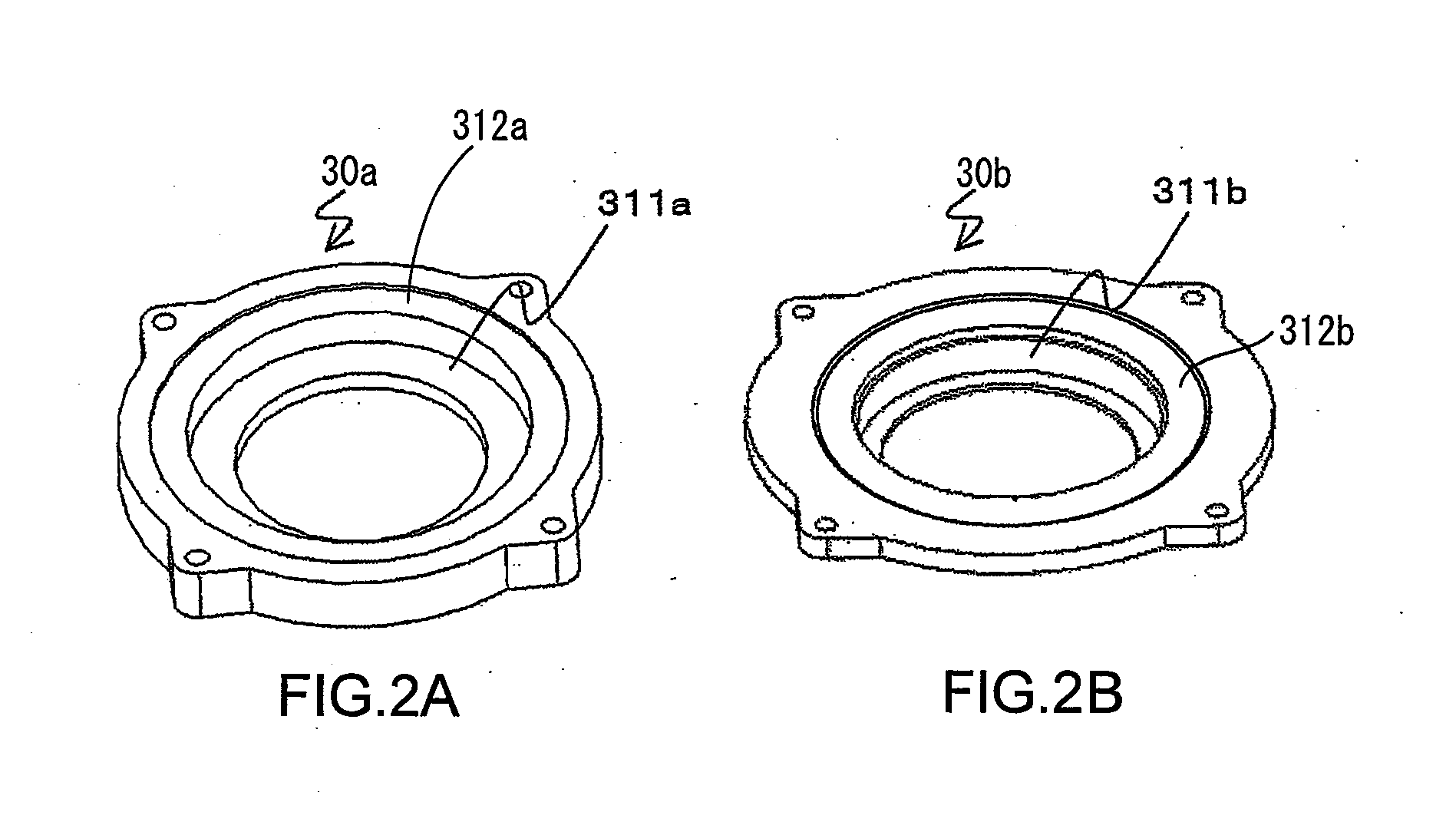
[0208]FIG. 1A is a perspective of the motor. FIG. 1B is an exploded perspective of the motor, showing individual end brackets, a rotor and a stator of the motor separately. FIG. 2A is a perspective of the end bracket located on an output shaft side and FIG. 2B is a perspective of the end bracket located on the opposite end along the axial direction relative to the end b...
second embodiment
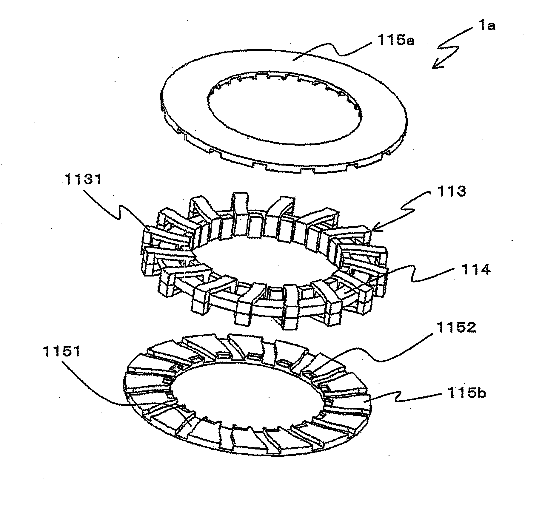
[0250]The second embodiment of the present invention is now described. FIG. 10A is a perspective showing a block holding surface of a holding plate 115, FIG. 10B is a perspective showing the rear surface of one of the holding plates, i.e., the holding plate 115a and FIG. 10C is a perspective showing the rear surface of the other holding plate 115b. FIG. 11A is a perspective of the end bracket 30a located on the output shaft side, whereas FIG. 11B is a perspective of the end bracket 30b located on the opposite end along the axial direction relative to the end bracket 30a in FIG. 11A. It is to be noted that while the second embodiment differs from the first embodiment in the structures assumed for the holding plates 115 and the end brackets 30a and 30b, other structural features are substantially identical to those in the first embodiment. Accordingly, the same terms and reference numerals are assigned to identical components so as to preclude the necessity for a repeated explanation ...
third embodiment
[0256]Next, the third embodiment of the present invention is described in reference to FIGS. 12A and 12B. FIG. 12A is a perspective showing the block holding surface over which the blocks are held at a holding plate 115, where as FIG. 12B is a perspective showing the surface of one of the holding plates, i.e., the holding plate 115a, on the side opposite from its holding surface. It is to be noted that while the holding plates 115 in the third embodiment differ from those in the second embodiment, other structural features of the third embodiment are substantially identical to those of the second embodiment. Accordingly, the same terms and reference numerals are assigned to identical components so as to preclude the necessity for a repeated explanation thereof.
[0257]While the holding plates 115 achieved in the third embodiment are very similar to the holding plates 115 in the second embodiment, they each further include passing holes 1157 through which the terminal lines of the stat...
PUM
 Abstract
Description
Claims
Application Information