
Image forming apparatus and image forming method performed by the image forming apparatus

a technology of image forming apparatus and forming apparatus, which is applied in the direction of electrographic process apparatus, instruments, optics, etc., can solve the problems of reducing development ability and transfer efficiency, degrading toner, and running the development unit for a rather long time without consuming an appropriate amount of toner, so as to reduce the cost of toner usage, effectively suppress or prevent the quality of image from degrading, and effectively suppress the effect of image quality degrading

Inactive Publication Date: 2009-01-01
RICOH KK
View PDF4 Cites 30 Cited by
  • Summary
  • Abstract
  • Description
  • Claims
  • Application Information

AI Technical Summary

Benefits of technology

[0013]Exemplary aspects of the present invention provide an image forming apparatus that can effectively reduce costs on toner usage by recycling residual toner remaining on a surface of an image carrier even after image transfer to a recording medium or an intermediate transfer member and that can effectively suppress or prevent quality of image from degrading due to accumulation of deteriorated toner in a developing unit.
[0014]Other exemplary aspects of the present invention provide an image forming apparatus that can effectively suppress or prevent quality of image from degrading due to accumulation of deteriorated toner in a developing unit.

Problems solved by technology

However, if a known image forming apparatus having such developing unit frequently produces an image having a low image area, the developing unit may be run for a rather long period of time without consuming an appropriate amount of toner.
As a result, the toner may be agitated excessively in the developing unit, which can degrade the toner.
Such degraded toners may contaminate a background part or non-image forming part on a surface of a recording medium, degrade development ability and transfer efficiency, etc., which can cause degradation of the quality of images such as contamination, degradation of image density, degradation of granularity, etc.
When a result of calculation is below a given threshold or when the toner contained in the developing unit is excessively agitated, the image forming apparatus forms a forcible toner consumption image to forcibly consume toner excessively agitated in the developing unit.
When it is determined based on the area of the output image that the toner has been excessively agitated, the image forming apparatus may form the forcible toner consumption image to forcibly consume such toner.
Such residual toner is then removed from the surface of the image carrier by a residual toner removal unit since, if the residual toner is discarded, unnecessary toner consumption may be conducted.
The above-described configuration, however, cannot sufficiently prevent accumulation of degraded toner particles in the developing unit because even though the toner particles excessively agitated in the developing unit are discharged from the developing unit by the formation of the forcible toner consumption image, the residual toner removal unit may still remove the forcible toner consumption image from the surface of the image carrier and returns the excessively agitated toner into the developing unit.
Thus, the excessively agitated toner particles may continue to accumulate in the developing unit, defeating the purpose of employing the forcible toner consumption image in the first place.

Method used


Image

  • Image forming apparatus and image forming method performed by the image forming apparatus
  • Image forming apparatus and image forming method performed by the image forming apparatus
  • Image forming apparatus and image forming method performed by the image forming apparatus

Examples


example 1

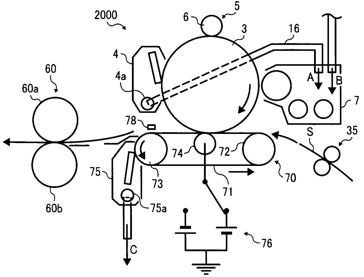
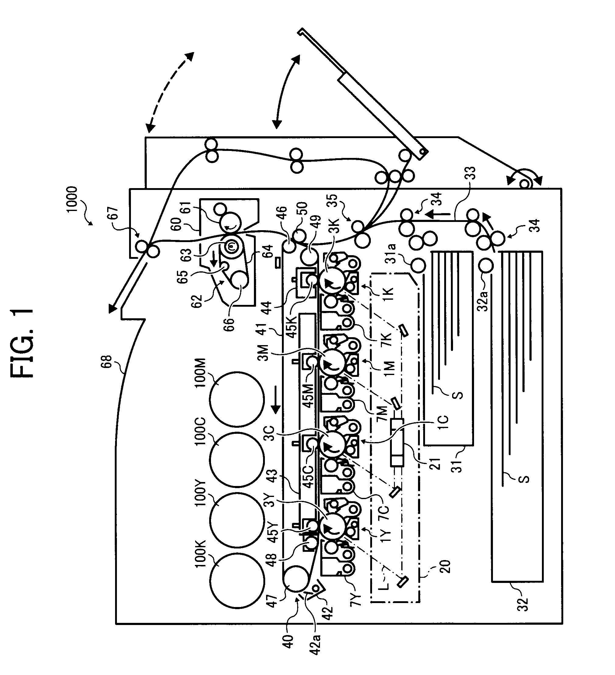
[0197]In reference to FIG. 1, the forcible toner consumption images of yellow, cyan, magenta, and black toners are transferred from the photoconductors 3Y, 3C, 3M, and 3K to the intermediate transfer belt 41 in the primary transfer process, and pass a position opposite the secondary transfer roller 50 before a position for cleaning the toner by the belt cleaning unit 42. At this time, if the secondary transfer roller 50 serving as a contact member contacts the intermediate transfer belt 41 with the secondary transfer nip is formed, it is likely that the forcible toner consumption images of yellow, cyan, magenta, and black toners transfer to the secondary transfer roller 50.

[0198]To avoid the transfer of the forcible toner consumption images, a contact and separation unit 90 shown in FIG. 12 is provided to the printer 1000 according to Example 1 of the first exemplary embodiment.

[0199]The contact and separation unit 90 causes the secondary transfer roller 50 to contact to and separat...

example 2

[0201]As described above, the printer 1000 according to Example 1 of the first exemplary embodiment can avoid the background contamination on the recording sheet S. In Example 2, instead of installing the contact and separation unit 90, the printer 1000 of Example 2 varies polarities of a secondary transfer bias, so that the overall machine size can be smaller.

[0202]FIG. 13 illustrates an example of timing charts showing drive timings of the optical writing unit 20, the primary transfer rollers 45Y, 45C, 45M, and 45K, and the secondary transfer roller 50 for a single job of producing one print in a full-color print mode of the printer 1000, when the M-toner consumption flag is set.

[0203]Shortly after the optical writing processes for the photoconductors 3Y, 3C, 3M, and 3K have started, respective primary transfer biases are applied to the primary transfer rollers 45Y, 45C, 45M, and 45K for a given time period. According to the application of the primary transfer biases, the Y-toner ...

example 3

[0306]The printer 2000 according to Example 3 executes the forced toner consumption process for each of the process units 1Y, 1C, 1M, and 1K when necessary, as shown in FIG. 23. Toner images formed on the photoconductors 3Y, 3C, 3M, and 3K of the process units 1Y, 1C, 1M, and 1K, respectively, are primarily transferred onto the intermediate transfer belt 41.

[0307]Of the process units 1Y, 1C, 1M, and 1K, the process unit 1Y for forming Y-toner image is disposed at the extreme upstream side in a direction of movement of the intermediate transfer belt 41, and therefore the toner image formed on the photoconductor 3Y may be a first image to be transferred onto the intermediate transfer belt 41 during a primary transfer process and the photoconductor 3Y may be a first image carrier to move to the primary transfer roller 45Y for the primary transfer process. In such configuration, the deteriorated Y-toner included in the forcible toner consumption image transferred from the photoconductor...


PUM


Abstract

An image forming apparatus, in which an image forming method is performed, includes an image carrier, an optical writing unit, a developing unit developing a toner image including an output image and a forcible toner consumption image, a transfer unit including an endless moving member to transfer the toner image onto the endless moving member directly or a recording medium carried on the endless moving member, a first remover to remove residual toner from the image carrier after transfer, a toner recycling unit to convey the residual toner to the developing unit, a controller to form the forcible toner consumption image and transfer the forcible toner consumption image onto the surface of the endless moving member, and a second remover to remove the forcible toner consumption image from the endless moving member.

Description

CROSS-REFERENCE TO RELATED APPLICATIONS[0001]The present patent application claims priority under 35 U.S.C. §119 from Japanese Patent Application No. 2007-170119, filed on Jun. 28, 2007 in the Japan Patent Office, the contents and disclosure of which are hereby incorporated by reference herein in their entirety.BACKGROUND OF THE INVENTION[0002]1. Field of the Invention[0003]Exemplary embodiments of the present invention generally relate to an image forming apparatus and an image forming method performed by the image forming apparatus, and more particularly, to an image forming apparatus that forms a forcible toner consumption image on an image carrier when necessary to forcibly consume toner contained in developer contained in a developing unit, and an image forming method performed by the image forming apparatus.[0004]2. Discussion of the Related Art[0005]Related-art image forming apparatuses such as copiers, facsimile machines, and printers include a developing unit for containing...

Claims


Application Information

Patent Timeline
Patent Type & Authority Applications(United States)
IPC IPC(8): G03G15/16G03G21/00
CPCG03G15/0844G03G15/1605G03G21/105G03G15/161
Inventor ENDOU, OSAMUTANO, ATSUSHI
Owner RICOH KK
Learn More