
Methods and systems for dynamic generation of filters using a graphical user interface

a filter and user interface technology, applied in the field of methods and systems for dynamic filter generation, can solve the problems of restricting limiting the ability of administrators, and allowing administrator complete freedom in filter definition

Inactive Publication Date: 2009-01-01
CITRIX SYST INC
View PDF99 Cites 62 Cited by
  • Summary
  • Abstract
  • Description
  • Claims
  • Application Information

AI Technical Summary

Benefits of technology

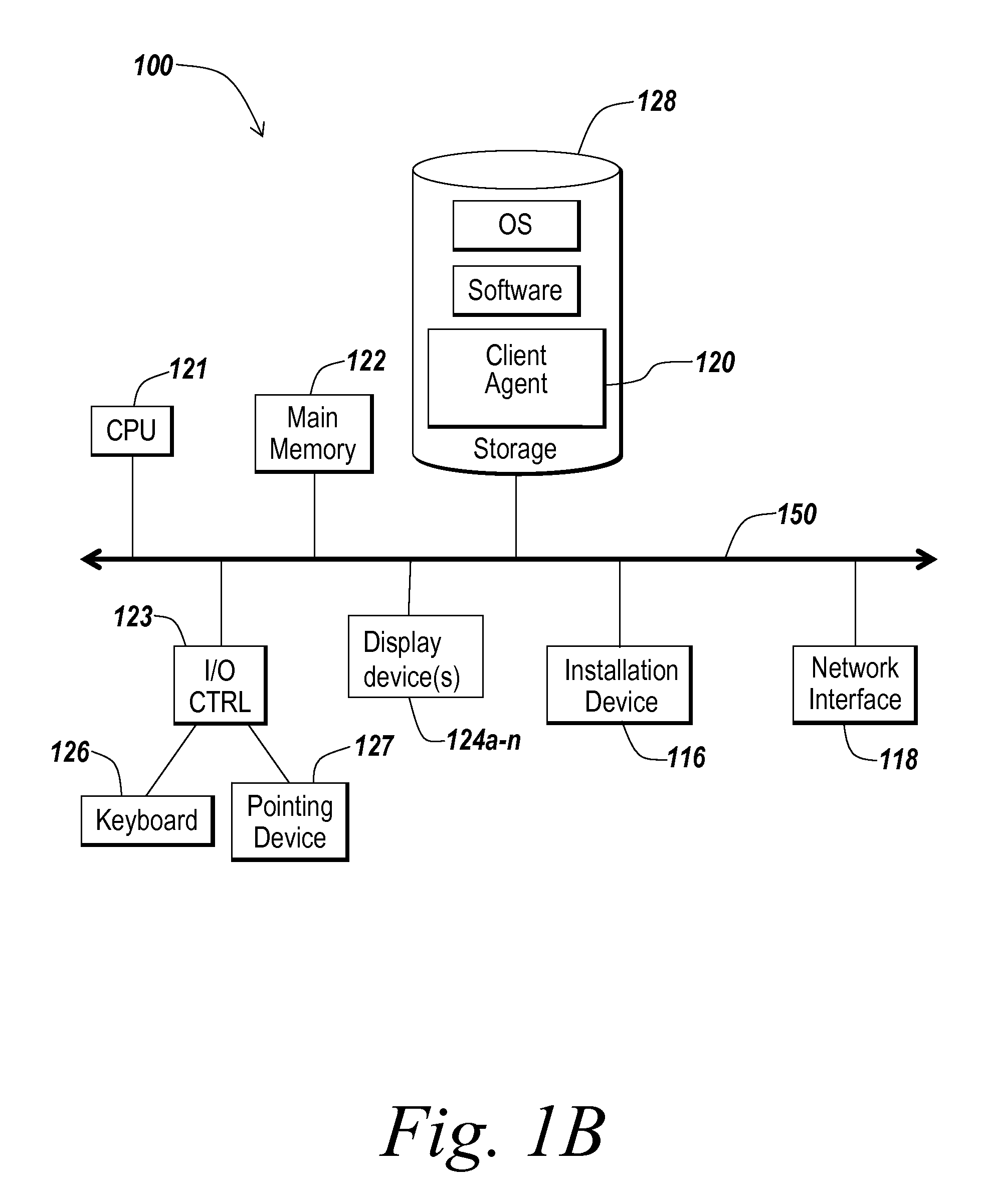
[0009]FIGS. 1B and 1C are block diagrams depicting embodiments of computers useful in connection with the methods and systems described herein;

Problems solved by technology

Typically, many administrative tools avoid giving the administrator complete freedom in defining filters, as there is a danger of confusing the administrator or, worse, creating filters that are difficult for the administrator to understand and manage.
However, limiting an administrator's ability to define filters may make it harder for the administrator to specify complex but valid conditions.

Method used


Image

  • Methods and systems for dynamic generation of filters using a graphical user interface
  • Methods and systems for dynamic generation of filters using a graphical user interface
  • Methods and systems for dynamic generation of filters using a graphical user interface

Examples


Embodiment Construction

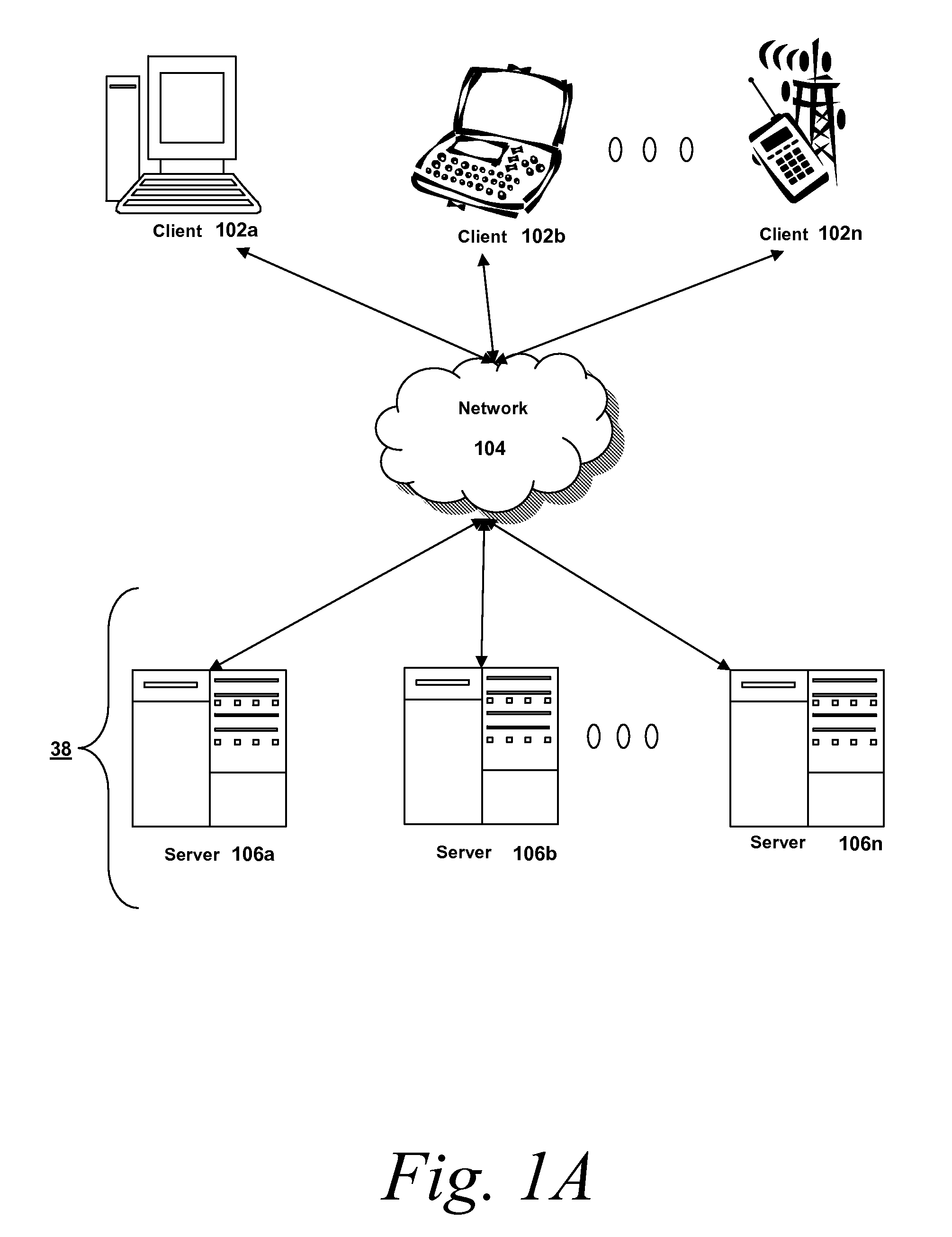
[0023]Referring now to FIG. 1A, an embodiment of a network environment is depicted. In brief overview, the network environment comprises one or more clients 102a-102n (also generally referred to as local machine(s) 102, or client(s) 102) in communication with one or more servers 106a-106n (also generally referred to as server(s) 106, or remote machine(s) 106) via one or more networks 104.

[0024]Although FIG. 1A shows a network 104 between the clients 102 and the servers 106, the clients 102 and the servers 106 may be on the same network 104. The network 104 can be a local-area network (LAN), such as a company Intranet, a metropolitan area network (MAN), or a wide area network (WAN), such as the Internet or the World Wide Web. In some embodiments, there are multiple networks 104 between the clients 102 and the servers 106. In one of these embodiments, a network 104′ may be a private network and a network 104 may be a public network. In another of these embodiments, a network 104 may b...


PUM


Abstract

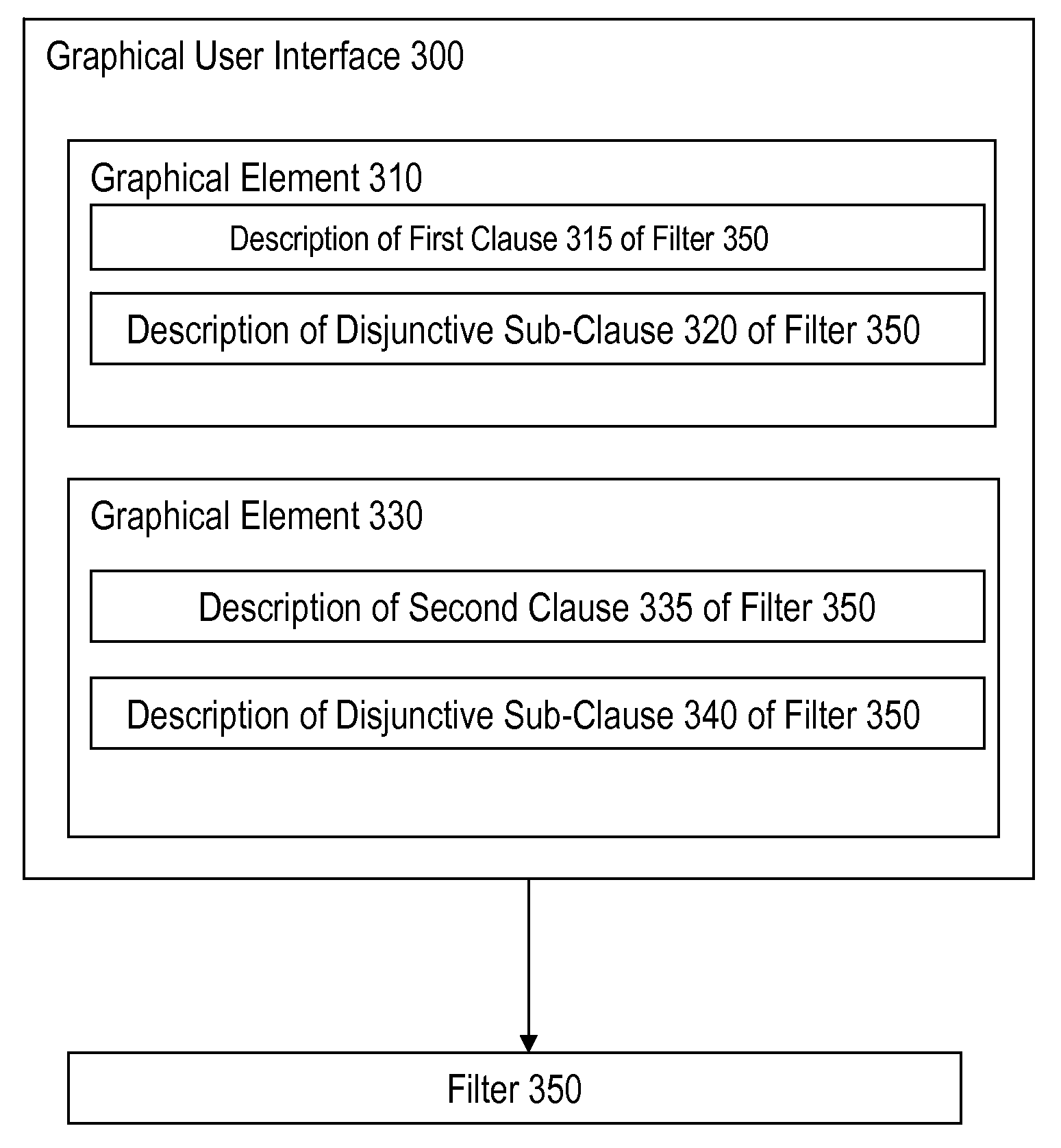
A method for dynamic generation of filters using a graphical user interface includes the step of describing a first clause of a filter in a first graphical user interface element. At least one of: i) a conjunctive clause of the filter in a second graphical user interface element, and ii) a disjunctive sub-clause of the first clause of the filter in the first graphical user interface element, are described. A filter is generated, responsive to the contents of the first graphical user interface element and the second graphical user interface element.

Description

FIELD OF THE INVENTION[0001]The present invention relates to methods and systems for generating filters. In particular, the present invention relates to methods and systems for dynamic generation of complex filters using a graphical user interface.BACKGROUND OF THE INVENTION[0002]Administrators granting users access to resources may need to manage complex filters defining user access rights. An administrator may use a filter editor to generate Boolean expressions defining a filter. Typically, many administrative tools avoid giving the administrator complete freedom in defining filters, as there is a danger of confusing the administrator or, worse, creating filters that are difficult for the administrator to understand and manage. Typical administrative tools force the administrator to create filters of a fixed structure, for example, a list of conditions all of which must apply (implicit AND) or a list of conditions at least one of which must apply (implicit OR). However, limiting a...

Claims


Application Information

Patent Timeline
Patent Type & Authority Applications(United States)
IPC IPC(8): G06F3/048
CPCG06F8/34G06F21/604H04L63/0227G06F2221/2105G06F2221/2141G06F21/6218
Inventor HAYTON, RICHARD
Owner CITRIX SYST INC
Learn More