Marine acoustic sensor assembly

a technology of acoustic sensor and assembly, which is applied in the direction of audible signalling system, instruments, specific gravity measurement, etc., can solve the problems of diminishing or eliminating internal reflections, and achieve the effect of reducing or eliminating sound inciden

Inactive Publication Date: 2009-01-08
UNITED STATES OF AMERICA
View PDF6 Cites 4 Cited by
  • Summary
  • Abstract
  • Description
  • Claims
  • Application Information

AI Technical Summary

Benefits of technology

[0007]Accordingly, an object of the invention is to provide a marine acoustic sensor assembly which measures substantially only the sound incident on the forward surface of the acoustic panel, while greatly decreasing, or eliminating, sound incident on the after surface of the acoustic panel.
[0008]With the above and other objects in view, a feature of the present invention is the provision of a marine acoustic sensor assembly comprising an acoustic panel having a forward surface and an after surface, a laser scanner disposed proximate and removed from the acoustic panel after surface, the laser scanner being oriented so as to project a laser beam onto the acoustic panel after surface, and a sensor disposed and oriented so as to receive reflections of the laser beam off the acoustic panel and to transmit data from which a position of a sound generating source can be determined, wherein the acoustic panel is provided with an absorber layer extending over the after surface of the acoustic panel, and wherein the absorber layer is provided with holes extending therethrough, the holes being of a size sufficient to permit passage of the laser beams therethrough to the acoustic panel after surface and the reflections to pass therethrough and to the sensor, whereby to minimize reflections and noise originating from aft of the after surface, while permitting sound incoming from forward of the acoustic panel to be measured.

Problems solved by technology

Because the system cannot distinguish between incoming sound and noise, there is a need to diminish or eliminate internal reflections that are otherwise detected.

Method used


Image

  • Marine acoustic sensor assembly
  • Marine acoustic sensor assembly
  • Marine acoustic sensor assembly

Examples


Embodiment Construction

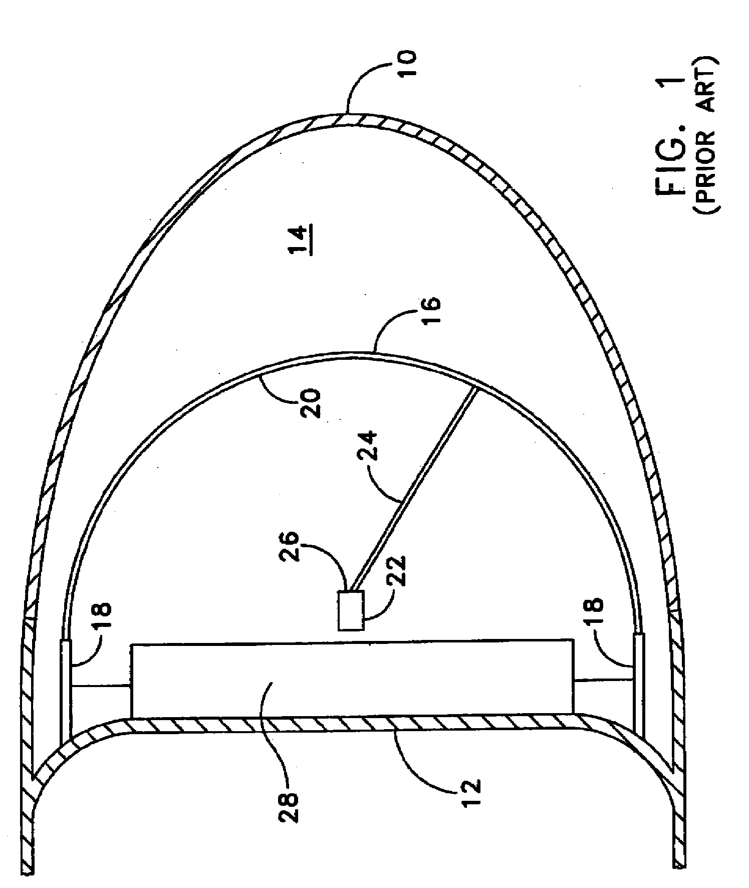
[0014]Referring to FIG. 1 it will be seen that a bow dome acoustic sensor assembly includes a forward-most outer hull portion 10 of the submarine or surface ship, known as the “bow dome”. Proximate the base of bow dome 10 is a pressure hull portion 12 extending athwartships and, in conjunction with bow dome 10, defining a zone 14.

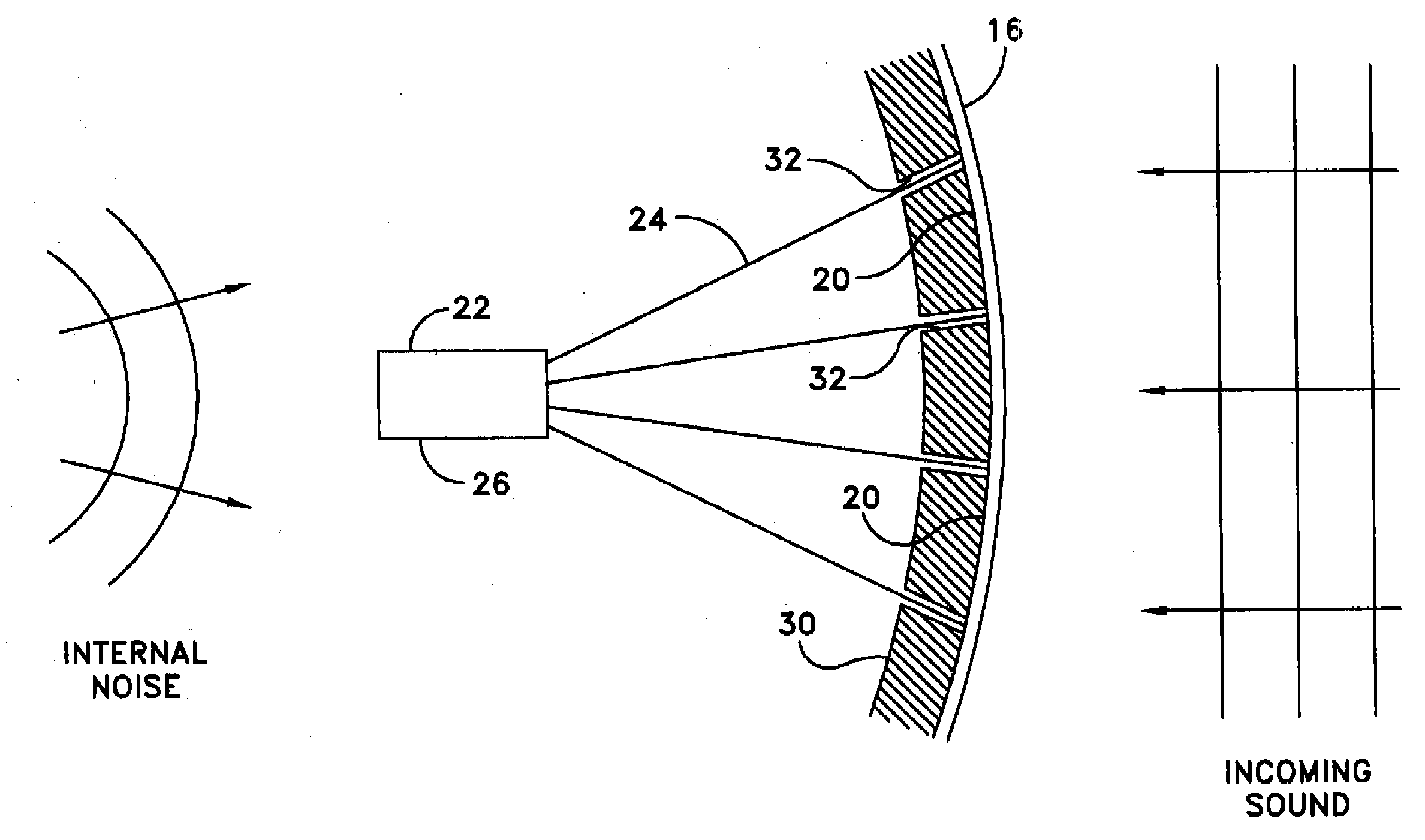
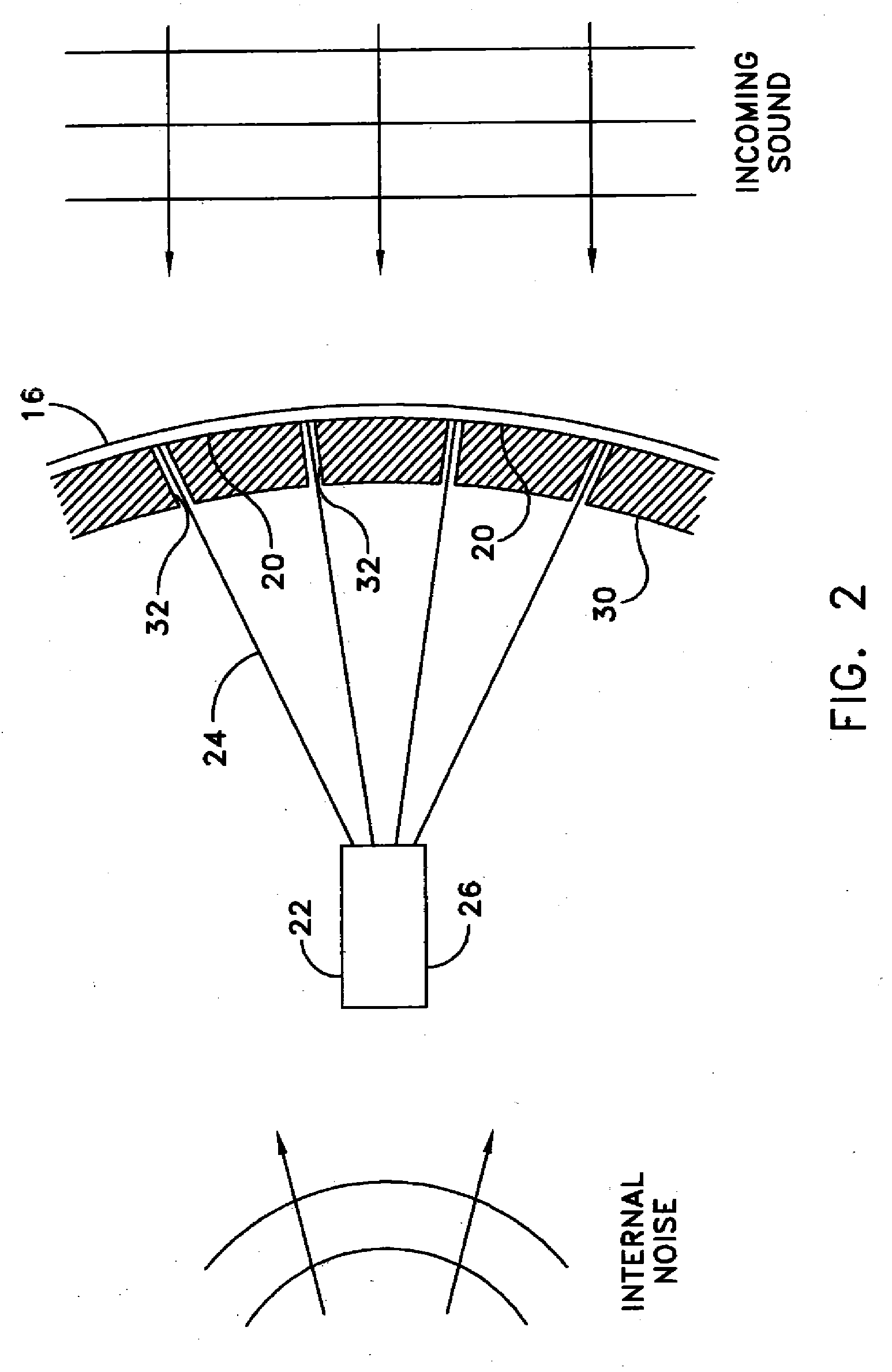
[0015]Disposed within the zone 14 is an acoustic panel 16 of lightweight rigid material, such as an aromatic polyamide material, or other relatively stiff plastic, or aluminum, or other material sufficiently rigid to be self supporting. The panel 16 is of a diameter such as to substantially fill the available space within the bow dome. The acoustic panel 16 is mounted on pressure hull portion 12 by way of acoustically isolating supports 18. An after surface 20 of the acoustic panel 16 is provided with optical properties which permit analysis of light from a laser, as is known in the art.

[0016]Further disposed within the zone 14 is a laser scanner 22 mounted...


PUM


Abstract

A marine acoustic sensor assembly includes an acoustic panel having a forward surface and an after surface, a laser scanner oriented so as to project a laser beam onto the acoustic panel after surface, and a sensor oriented so as to receive reflections of the laser beam off the acoustic panel and to transmit data from which a position of a sound generating source can be determined, wherein the acoustic panel is provided with an absorber layer extending over the after surface thereof, and the absorber layer is provided with holes extending therethrough, the holes being of a size sufficient to permit passage of the laser beams to the acoustic panel after surface and the reflections to pass to the sensor, whereby to minimize reflections and noise originating from aft of the after surface, while permitting sound incoming from forward of the acoustic panel to be measured.

Description

STATEMENT OF GOVERNMENT INTEREST[0001]The invention described herein may be manufactured and used by or for the Government of the United States of America for governmental purposes without the payment of any royalty thereon or therefore.BACKGROUND OF THE INVENTION[0002]1. Field of the Invention[0003]The invention relates to target detection and tracking apparatus and is directed more particularly to an acoustic sensor assembly for detecting and tracking noise-producing and / or noise reflecting objects in an ocean environment.[0004]2. Description of the Prior Art[0005]Marine vessels, such as submarines and surface ships, are typically provided with acoustic sensor assemblies. In such assemblies a laser scanner is disposed and oriented so as to project a laser beam onto an after surface of an acoustic panel, the sensor being disposed and oriented so as to receive reflections of the laser beam off the acoustic panel and to transmit data from which a position of a sound generating source...

Claims


Application Information

Patent Timeline
Patent Type & Authority Applications(United States)
IPC IPC(8): G10K11/00G01H9/00
CPCG01H9/002
Inventor RUFFA, ANTHONY A.
Owner UNITED STATES OF AMERICA
Why Eureka
Try Eureka