

Spring Seat of Suspension
a technology of spring seat and suspension, which is applied in the direction of mechanical equipment, twisting springs, transportation and packaging, etc., can solve the problems of difficulty in enhancing driving performance and stability by obtaining characteristics exactly as designed, and achieve the effect of restricting the adjustment of tire position
- Summary
- Abstract
- Description
- Claims
- Application Information
AI Technical Summary
Benefits of technology
Problems solved by technology
Method used
Image

Examples
first embodiment
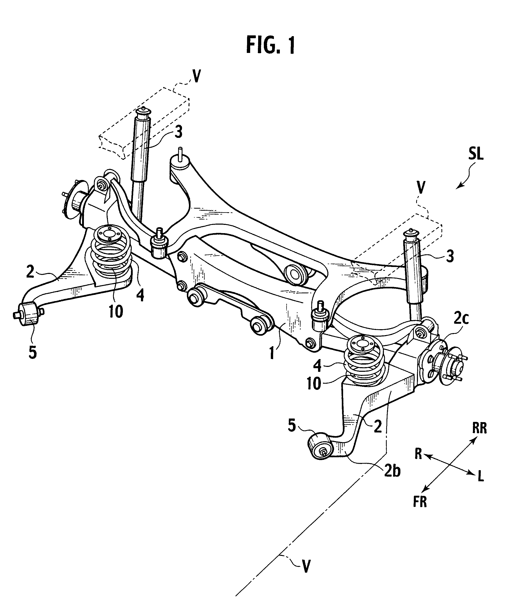
[0032]FIG. 1 is a perspective view showing a suspension link SL according to an embodiment of the present invention.
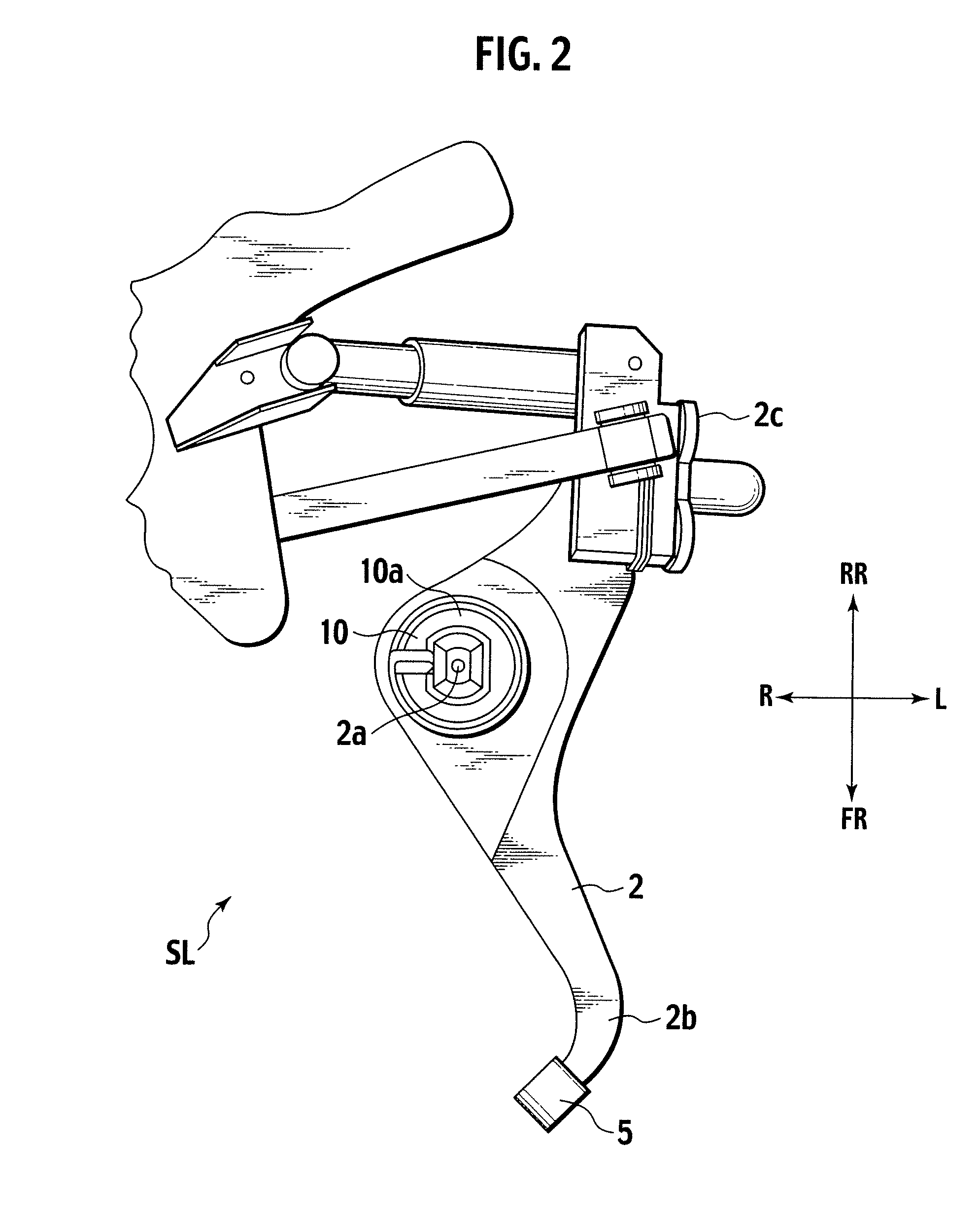
[0033]In the suspension link SL, as shown in FIG. 1, a suspension member 1 is arranged in the width direction of the vehicle. Trailing arms (or suspension arms) 2 each extending in the front-rear direction of the vehicle are arranged in the light and left end portions of the suspension member 1, respectively. Shock absorbers 3 are attached to the rear portion of each trailing arm 2 in the front-rear direction of the vehicle. Coil springs 4 are attached to the middle portion of each trailing arm 2 in the front-rear direction of the vehicle, which extend in top-bottom direction of the vehicle. Trailing arm bushes 5 are attached to the front portion of each trailing arm 2 in the front-rear direction of the vehicle.
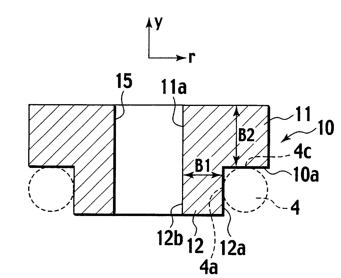
[0034]The bottom ends of the coil springs 4 are attached to the tops of spring seats 10 provided to the trailing arms 2, respectively. In addition, other spring...
second embodiment
[0052]FIGS. 6A and 6B each shows a spring seat 210 according a second embodiment.
[0053]As shown in FIGS. 6A and 6B, a space part 21 is made inside the spring seat 210. The space part 21 includes: a space part 21a, formed inside the main body part 11, which extends inward in the radial direction from the outer peripheral end of the main body part 11; and a space part 21b, formed inside the protrusion part 12, which extends in the axial direction, and which communicates with the space part 21a. The space part 21a is open outward of the spring seat 210 in its outside end in the radial direction thereof, and thus plays a role as a slit to have the space 21b communicated with the outside of the spring seat 210. It does not matter whether or not the space parts 21a and 21b continue in the circumferential direction of the spring seat 210, as long as the space parts 21a and 21b communicate with the outside. In addition, various cross-sectional shapes can be adopted for the space part 21 dep...
third embodiment
[0054]FIGS. 7A and 7B show a spring seat 310 according to the third embodiment.
[0055]As shown in FIGS. 7A and 7B, the spring seat 310 includes a protrusion part 31 which is formed in integration with the main body part 11, which juts out downward from the circumferential portion of the through-hole on the bottom surface of the main body part 11, and which has a cylindrical inner circumferential surface 32a in the center of the protrusion part 31. The protrusion part 31 is constructed in a double-wall structure which includes an inner circumferential wall 32 and an outer circumferential wall 33. An annular space part 34, which is open downward, is formed inside the protrusion part 31, or between the inner circumferential wall 32 and the outer circumferential 33. In this case, the inner circumferential surface 32a of the inner circumferential wall 32 along with the inner circumferential surface 11a of the main body part 11 constitutes the fitting hole 15 into which the fitting convex ...
PUM
 Abstract
Description
Claims
Application Information