Motor using magnetic normal force

a technology of normal force and motor, applied in the field of motors, can solve the problems of self-destructive system and disadvantage of extra mechanical conta

Inactive Publication Date: 2009-01-08
BOREALIS TECH LTD
View PDF2 Cites 28 Cited by
  • Summary
  • Abstract
  • Description
  • Claims
  • Application Information

AI Technical Summary

Benefits of technology

The patent aims to use the strong radial magnetic force in the steel core of conventional induction motors to drive an induction motor, instead of using the smaller tangential force produced in the windings. This would provide a more efficient and effective way to utilize the magnetic force.

Problems solved by technology

The patent text describes various configurations of motors and generators that use different methods to produce high torque and variable speed. The technical problem addressed in the text is the need for a motor that can provide high torque and rotate at a high speed to provide a compact and efficient system for vehicles. The text also discusses the use of gears and other mechanisms to optimize the performance of the motor. The patent text describes various methods for controlling and optimizing the motor to improve its performance. The text also describes the use of gears to increase or decrease the output speed or torque of the motor. The use of multiple configurations of motors and generators is also discussed, along with different methods for inducing torque and current using magnetic force and speed reduction drive train. The text also describes the use of gears and other mechanisms to improve the performance of the motor. The use of a rolling rotor and a stator to provide a more effective and efficient system for vehicles. The patent text also discusses various methods for controlling and optimizing the motor. The technical problem addressed in the patent text is the need for a motor that can provide high torque and speed in a compact and efficient system for vehicles.

Method used


Image

  • Motor using magnetic normal force
  • Motor using magnetic normal force
  • Motor using magnetic normal force

Examples


first embodiment

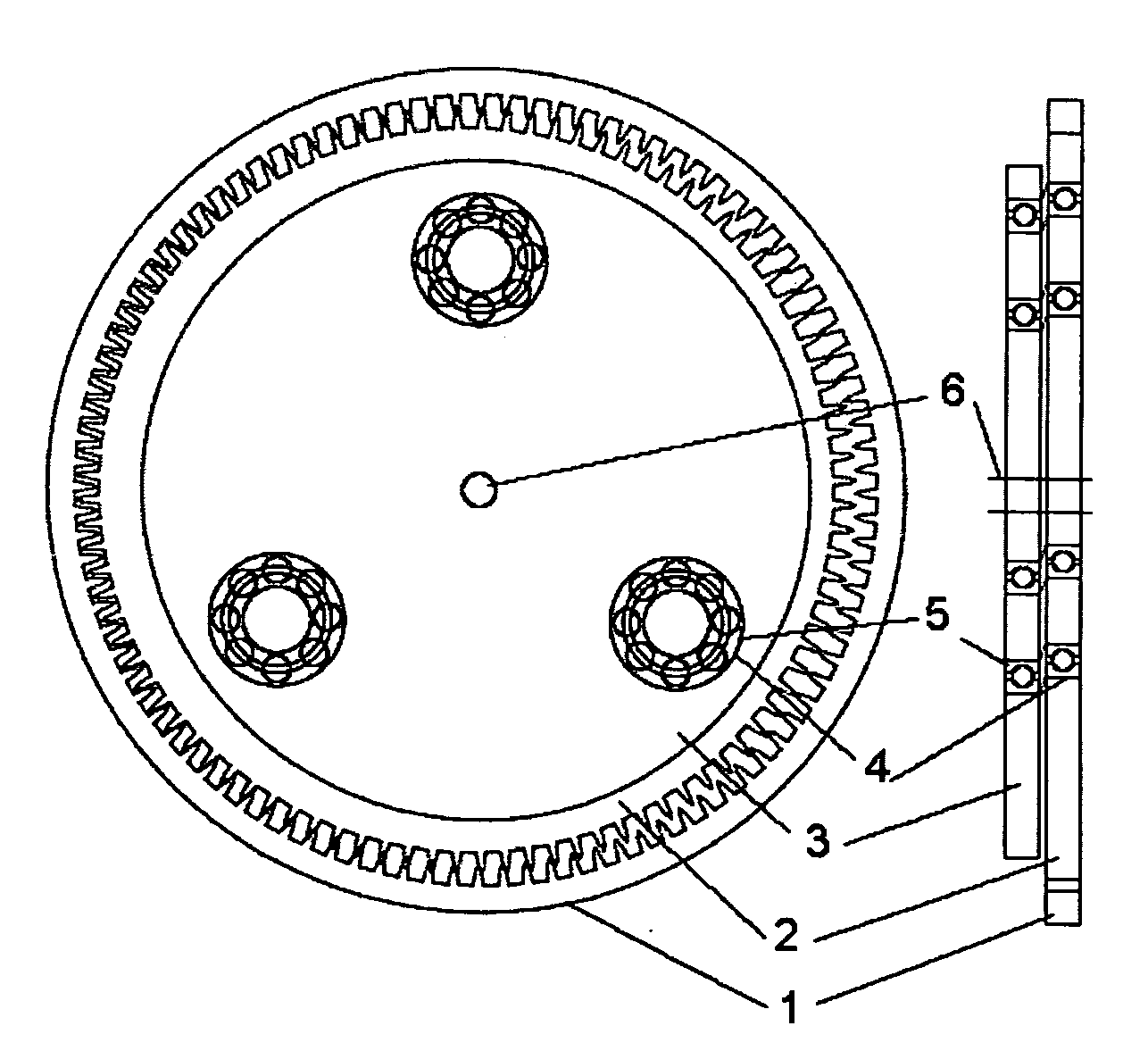
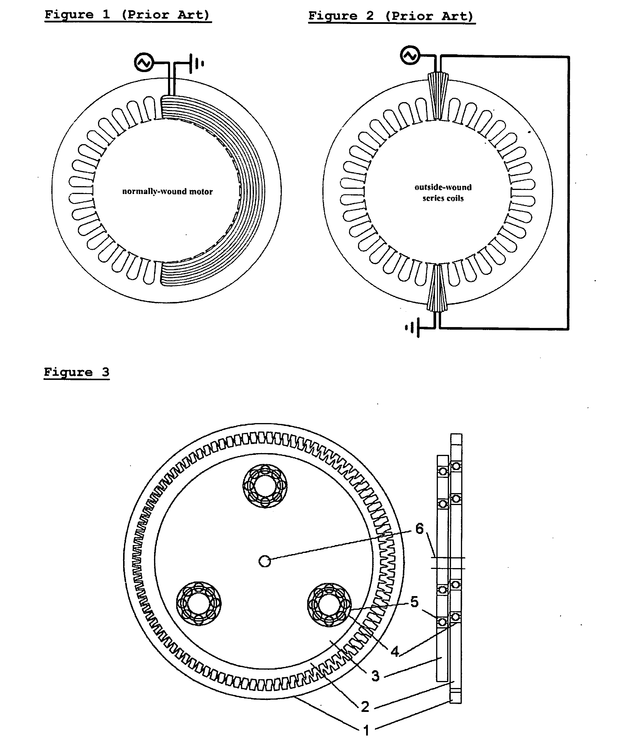
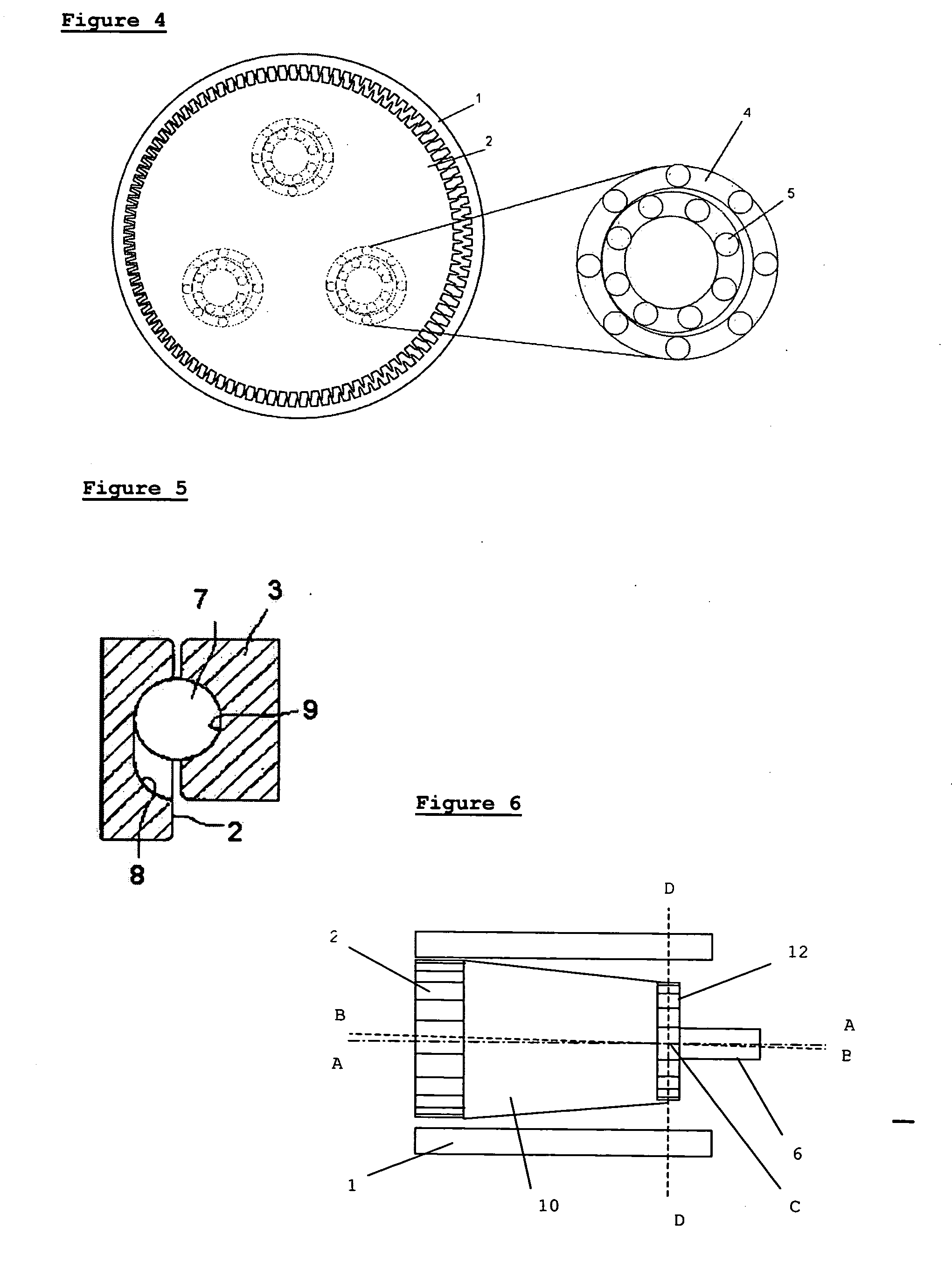
[0051]In the invention, a motor is disclosed, comprising a stator of high permeability material having a magnetic core, magnetic windings, and an internal cavity which is preferably cylindrical; and a rotor made from ferromagnetic materials with high permeability, situated inside the stator. Preferably, said rotor is internal to said stator and said rotor has an outer diameter significantly smaller than the inner diameter of the stator. The outer diameter of the rotor and the inner diameter of the stator have gear teeth so that the rotor and stator mesh as eccentric gears.

[0052]Preferably, said windings comprise a set of electrical coils positioned in slots, channels, or cavities in the high permeability material. The coils are arranged to induce a magnetic field in the high permeability material of the rotor and stator and any gap between, thereby creating magnetic attractive force between the rotor and the stator.

[0053]During operation, the stator windings are selectively and sequ...

second embodiment

[0098]In the invention, shown in FIG. 15, a motor comprises a stator 1 having a magnetic core, magnetic windings 22 (only one shown for clarity), and a cylindrical internal cavity; an eccentric rotor 2 eccentrically mounted inside the stator; and a flexible spline 30 (as known in the field of harmonic gearing), concentrically mounted inside the stator and coupled both to the rotor and to an output shaft 6. The motor is mounted on a bearing and can rotate.

[0099]During operation, the stator is magnetized in such a way that the rotor is pulled around the internal cavity of the stator, eccentrically oscillating at high frequency and rotating. Since the rotor is coupled to the spline, the spline rotates with the rotor but flexes to accommodate the eccentric oscillation of the rotor, thus only the rotation is transmitted by the spline to the output shaft. An advantage of this arrangement is that the motor can be integrally combined with the gearing.

[0100]Preferably, the internal surface o...

fourth embodiment

[0123]In the invention, shown in FIG. 18, a motor is disclosed, comprising a stator 1 having a magnetic core, magnetic windings, and a cylindrical internal cavity; and an eccentric ring gear rotor 37 made from magnetically attractive materials, situated inside the stator. The eccentric ring gear rotor has an outer diameter significantly smaller than the inner diameter of the stator and is internally and externally toothed. A smaller gear 38 is situated inside the ring gear rotor, concentric with the stator, mounted on the output shaft. The outer diameter of the smaller concentric gear 38 and the inner diameter of the stator 1 have gear teeth. The eccentric ring gear rotor 37 engages the stator on its outside and the smaller concentric gear on its inside. Thus the eccentric ring gear rotor connects the smaller concentric gear to the stator. In general, the gears are very similar in size, with the concentric gear 38 not much smaller than the innder diameter of the stator 1, and the ri...


PUM


Abstract

A motor is disclosed comprising: at least one stator comprising a magnetic core and at least one magnetic winding, having a cylindrical internal cavity; at least one cylindrical rotor inside said stator, comprising magnetically conductive materials; said rotor having an outer diameter significantly smaller than the inner diameter of said stator, being eccentrically mounted with respect to said stator and able to move within, said fixed member; wherein magnetic normal force is induced in said stator periodically, whereby said rotor is periodically moved by magnetic force with respect to said stator, whereby rotary motion is produced; said motor further having: an output shaft concentric with said stator; transmission means for absorbing oscillation and transmitting rotation; wherein said induced magnetic normal force rotates around the circumference of said stator, such that a contact patch between said rotor and said stator rotates around the inner circumference of said stator; whereby said rotor oscillates and rotates; whereby said transmission means absorb the oscillation of said rotor and transmit the rotation of said rotor to said output shaft; wherein said transmission means is magnetorheostatic fluid. A motor is further disclosed wherein said transmission means comprise bearings and carrier supports, wherein said bearings are used as a clutch.

Description


Claims


Application Information

Patent Timeline
Owner BOREALIS TECH LTD
Why Eureka
Try Eureka