User interface for ultrasound system

a technology of user interface and ultrasound system, which is applied in the field of ultrasound systems, can solve the problems of limited space available to the various controllers on the control portion, difficulty or complex control of certain procedures or adjust different parameters, and the insufficient control of ultrasound systems

Inactive Publication Date: 2009-01-08
GENERAL ELECTRIC CO
View PDF6 Cites 116 Cited by
  • Summary
  • Abstract
  • Description
  • Claims
  • Application Information

AI Technical Summary

Benefits of technology

[0006]In accordance with one embodiment, an ultrasound system is provided that includes a user interface having at least one user control member and a display having a plurality of virtual display elements displayed thereon when a virtual pointer is positioned over an image displayed on the display. A function controlled by the at least one user control member is determined based on a selected one of the plurality of virtual display elements.
[0007]In accordance with another embodiment, an ultrasound system is provided that includes an ultrasound volume probe for acquiring one of three-dimensional (3D) ultrasound data and four-dimensional (4D) ultrasound data and a portable control unit having a user interface and a display. The ultrasound volume probe is connected to the portable control unit and wherein manipulation of one of the 3D ultrasound data and 4D ultrasound data is provided by a single user control member of the user interface.

Problems solved by technology

As the size of ultrasound systems continue to decrease, the available space of the various controllers on the control portion is limited.
However, with the reduced space available in a compact unit, the reduced number of available control members can make it difficult or complex to control certain procedures or adjust different parameters.
In some instances, these portable ultrasound systems may not have enough controls to allow a user to control all of the operations that would otherwise be available on a larger system, but that are still desirable in portable systems.

Method used


Image

  • User interface for ultrasound system
  • User interface for ultrasound system
  • User interface for ultrasound system

Examples


Embodiment Construction

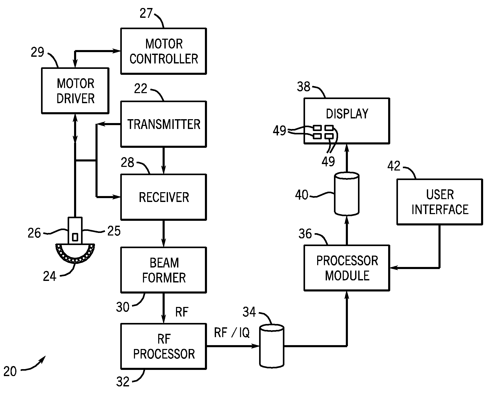
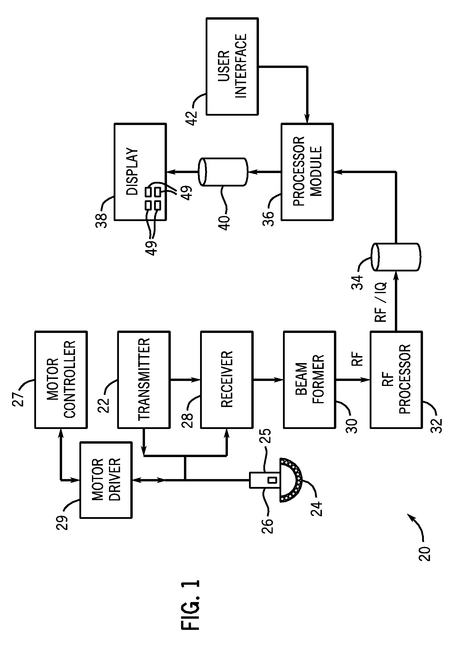
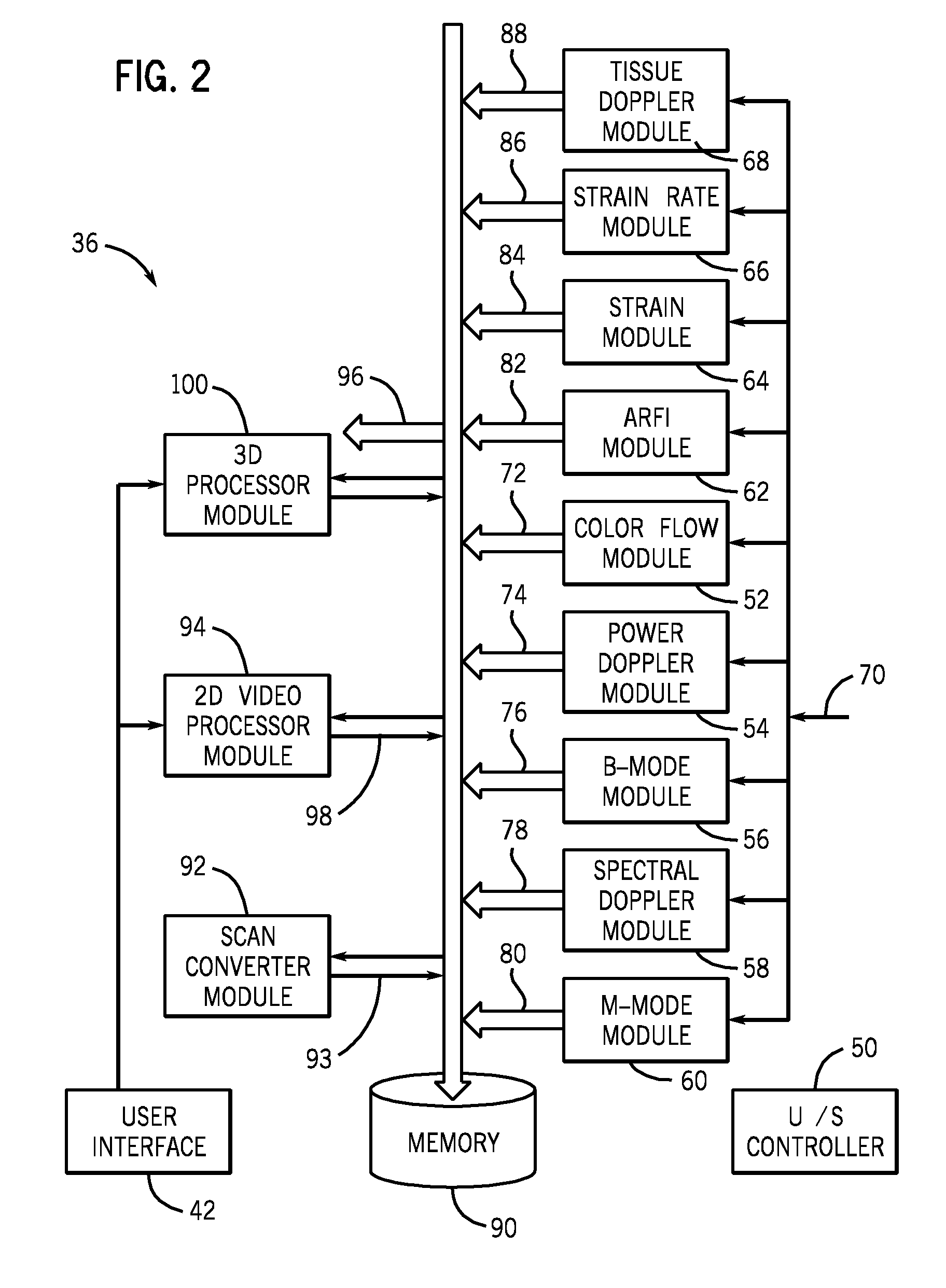
[0029]The foregoing summary, as well as the following detailed description of certain embodiments of the inventive arrangements, will be better understood when read in conjunction with the appended drawings. To the extent that the figures illustrate diagrams of the functional blocks of various embodiments, the functional blocks are not necessarily indicative of the division between hardware circuitry. Thus, for example, one or more of the functional blocks (e.g., processors or memories) may be implemented in a single piece of hardware (e.g., a general purpose signal processor or random access memory, hard disk, or the like). Similarly, the programs may be stand alone programs, may be incorporated as subroutines in an operating system, may be functions in an installed software package, and the like. It should be understood that the various embodiments are not limited to the arrangements and instrumentality shown in the drawings.

[0030]As used herein, an element or step recited in the ...


PUM


Abstract

A user interface for an ultrasound system is provided. The ultrasound system includes the user interface having at least one user control member and a display having a plurality of virtual display elements displayed thereon when a virtual pointer is positioned over an image displayed on the display. A function controlled by the at least one user control member is determined based on a selected one of the plurality of virtual display elements.

Description

CROSS-REFERENCE TO RELATED APPLICATIONS[0001]This application claims priority to and the benefit of the filing date of U.S. Provisional Application No. 60 / 914,893, filed Apr. 30, 2007 for “PORTABLE 3D / 4D ULTRASOUND,” which is hereby incorporated by reference in its entirety.BACKGROUND OF INVENTION[0002]This invention relates generally to ultrasound systems and, more particularly, to a user interface for controlling ultrasound imaging systems, especially portable ultrasound medical imaging systems.[0003]Ultrasound systems typically include ultrasound scanning devices, such as ultrasound probes having transducers that allow for performing various ultrasound scans (e.g., imaging a volume or body). The ultrasound probes are typically connected to an ultrasound system for controlling the operation of the probes. The ultrasound system usually includes a control portion (e.g., a control console or portable unit) that provides interfaces for interacting with a user, such as receiving user i...

Claims


Application Information

Patent Timeline
Patent Type & Authority Applications(United States)
IPC IPC(8): A61B8/00
CPCA61B8/13A61B8/4405A61B8/4427A61B8/463A61B8/483A61B8/467A61B8/469G01S7/52084A61B8/56A61B8/465A61B8/462A61B8/466
Inventor HOBELSBERGER, PETRADUDA, WALTER
Owner GENERAL ELECTRIC CO
Why Eureka
Try Eureka