Shock absorbing device for shoe sole

a technology of shock absorption and shoe sole, which is applied in the field of shock absorption device of shoe sole, can solve the problems of small young's modulus of viscoelastic materials such as resin foam, and the support of the rear foot portion may become unstable, and achieve the effect of enhancing the shock absorption function and softening the sole of the foo

Active Publication Date: 2009-01-15
ASICS CORP
View PDF11 Cites 85 Cited by
  • Summary
  • Abstract
  • Description
  • Claims
  • Application Information

AI Technical Summary

Benefits of technology

[0065]In this case, the shock of landing is dispersed by the relatively hard bending deformation member and more dispersed by the relatively soft connecting member. Thus, the function of dispersing the shock can be enhanced, and a soft sensation on the sole of the foot can be produced.

Problems solved by technology

However, in general, viscoelastic materials having small Young's modulus such as resin foam, which is commonly used as a cushioning member of shoe soles, cannot exhibit high restitution function because energy is dissipated as heat etc. at the time of deformation.
Thus, the support for the rear foot portion may become unstable.
However, these shoes may be hard to dissipate the shock and be unable to support the foot stably.
Therefore, impact energy cannot be stored in the oval spring sufficiently.

Method used


Image

  • Shock absorbing device for shoe sole
  • Shock absorbing device for shoe sole
  • Shock absorbing device for shoe sole

Examples


first embodiment

[0100]FIGS. 1 to 8 show the first embodiment.

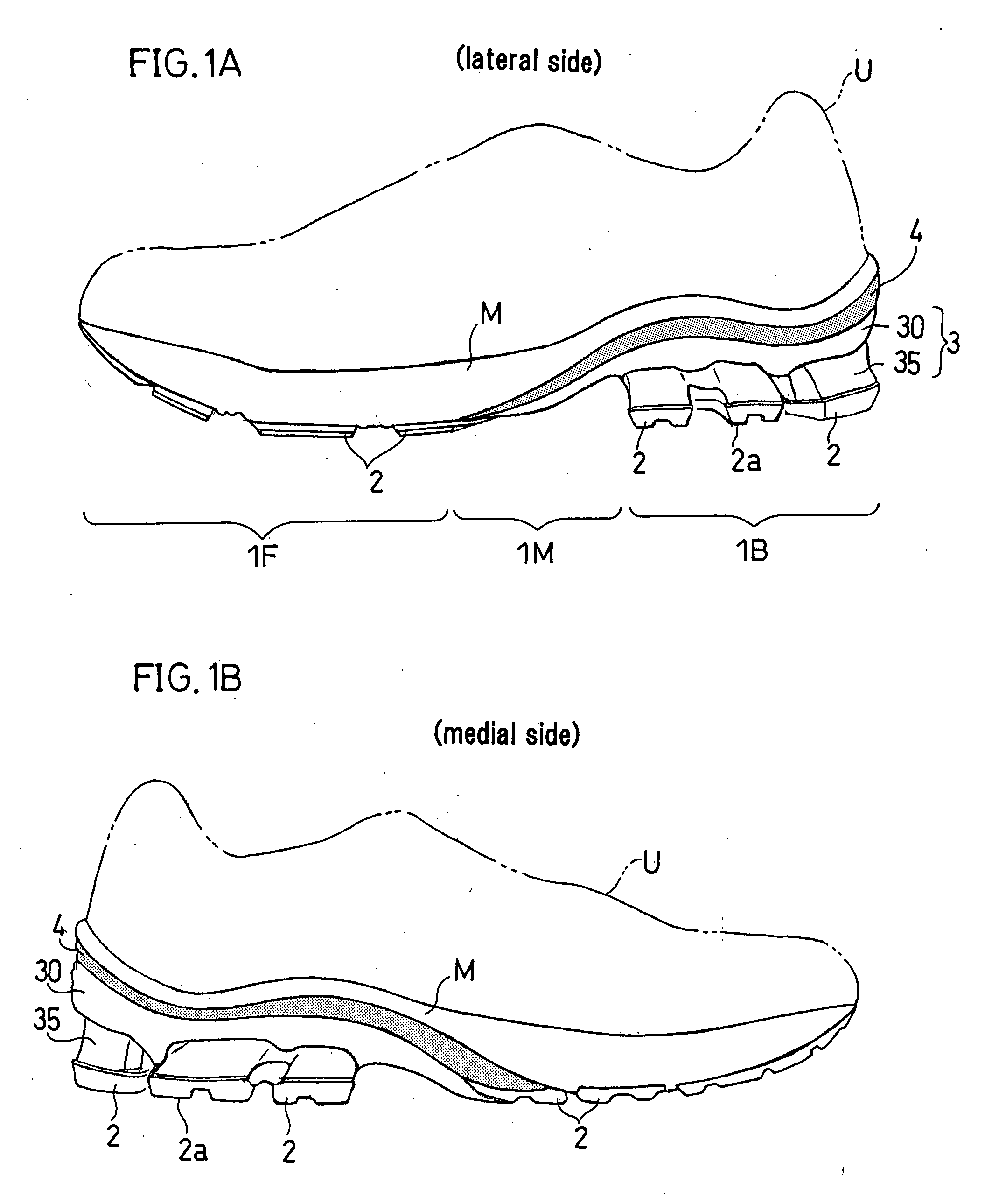
[0101]FIG. 1A shows a lateral side of the shoe (for a left foot) of the first embodiment and FIG. 1B shows a medial side of the same shoe.

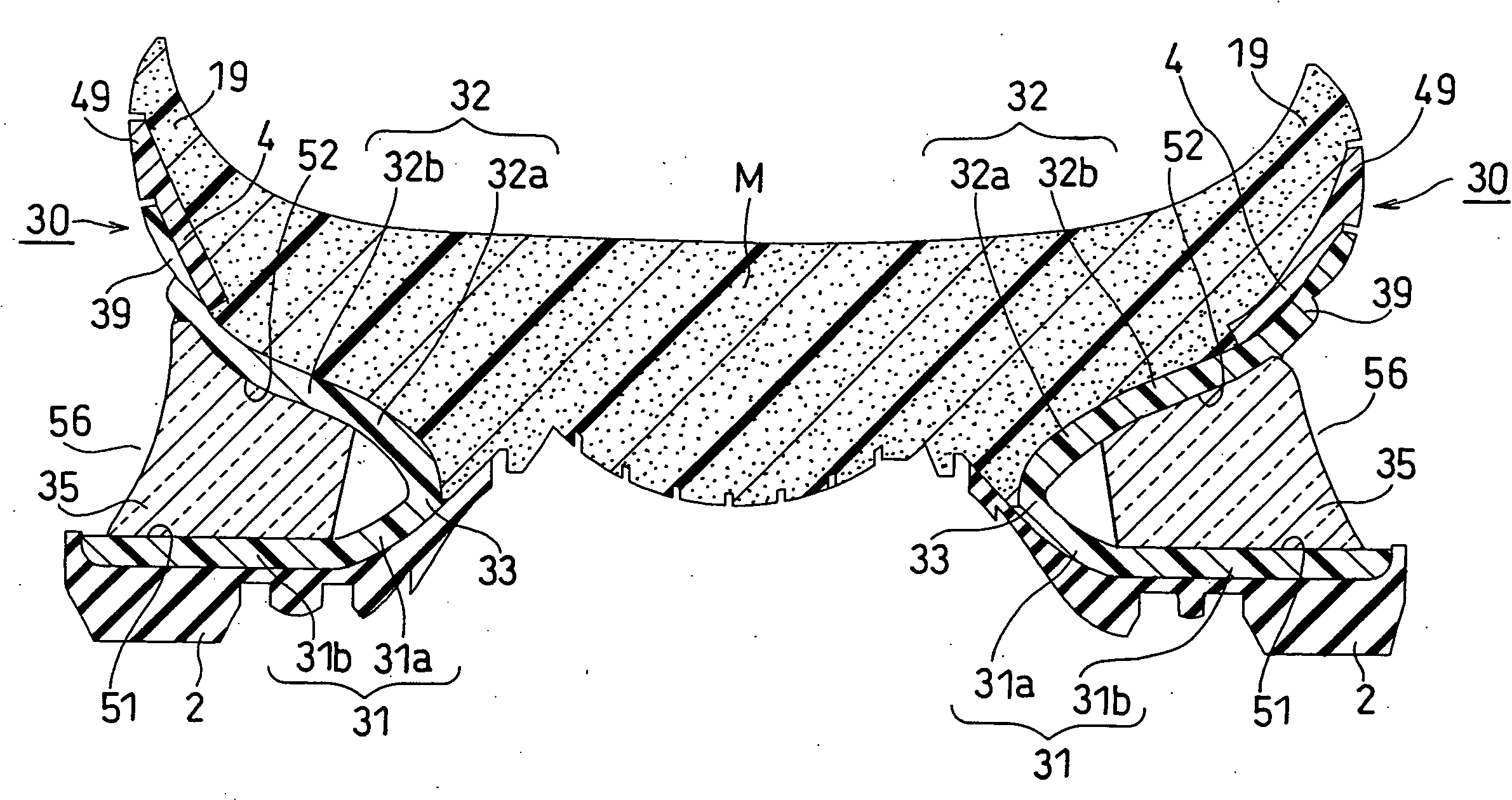
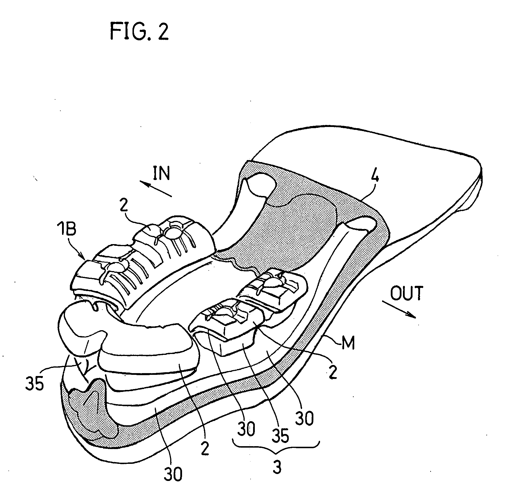
[0102]As shown in FIGS. 1A, 1B, the shoe sole of this embodiment includes an midsole M, an outer sole 2, a deformation element 3 and a connecting member 4. The deformation element 3 consists of a bending deformation member 30 and rubber-like members 35 (an example of a compression deformation member).

[0103]The outer sole 2 is joined to the bottom surface of the midsole M in the fore foot part (toe part) 1F. The connecting member 4 is joined to the bottom surface of the midsole M in an area extending from the mid foot part (arch part) 1M and the rear foot part (heel part) 1B. The upper surface of the bending deformation member 30 is joined to the bottom surface of the connecting member 4, and the rubber-like members 35 are arranged to be sandwiched between portions of the bending deformation member 30. T...


PUM


Abstract

A shock absorbing device for a shoe sole includes: an outer sole 2; a midsole M; and a deformation element 3 placed between the outer sole 2 and the midsole M. The deformation element 3 is positioned at a periphery of a rear foot part 1B and includes a bending deformation member 30 that opens toward the periphery from a center of the rear foot part 1B. The bending deformation member 30 includes a lower plate portion 31, an upper plate portion 32 that forms an opening angle with respect to the lower plate portion 31, and a curved portion 33 that connects the lower plate portion 31 and the upper plate portion 32. The lower plate portion 31 and the upper plate portion 32 are gradually getting away from each other as a distance from the curved portion increases. A rubber-like or pod-like compression deformation member 35 is fit between the lower and upper plate portions 31, 32. When an impact force of landing is loaded to the bending deformation member 30, the lower plate portion 31 and/or the upper plate portion 32 displaces or deflects in such a manner as to rotate about the curved portion 33 with the compression deformation member 35 being compressed.

Description

TECHNICAL FIELD[0001]The present invention relates to a shock absorbing device for shoe sole.BACKGROUND ART[0002]Shoe soles require a shock absorbing function of absorbing and cushioning shocks of landing in addition to lightness in weight and a function of stably supporting the foot. Recently, some shoes have been proposed, which includes a restitution function as well as above functions. The restitution function is a function wherein the shock energy at the time of landing is stored in a shoe sole as deformation energy and the stored deformation energy is released at the time of leaving the ground. This function serves to enhance athletic ability of a wearer.[0003]The deformation energy is stored in an element of the shoe sole by compression, bending or the like of the element. However, in general, viscoelastic materials having small Young's modulus such as resin foam, which is commonly used as a cushioning member of shoe soles, cannot exhibit high restitution function because ene...

Claims


Application Information

Patent Timeline
Patent Type & Authority Applications(United States)
IPC IPC(8): A43B13/18
CPCA43B13/181A43B13/189A43B13/187A43B13/183
Inventor NISHIWAKI, TSUYOSHIFUJITA, HISANORIKUROSAKI, KIYOMITSU
Owner ASICS CORP
Why Eureka
Try Eureka