

Dispenser Tap with Two Stage Valve
- Summary
- Abstract
- Description
- Claims
- Application Information
AI Technical Summary
Benefits of technology
Problems solved by technology
Method used
Image

Examples
first embodiment
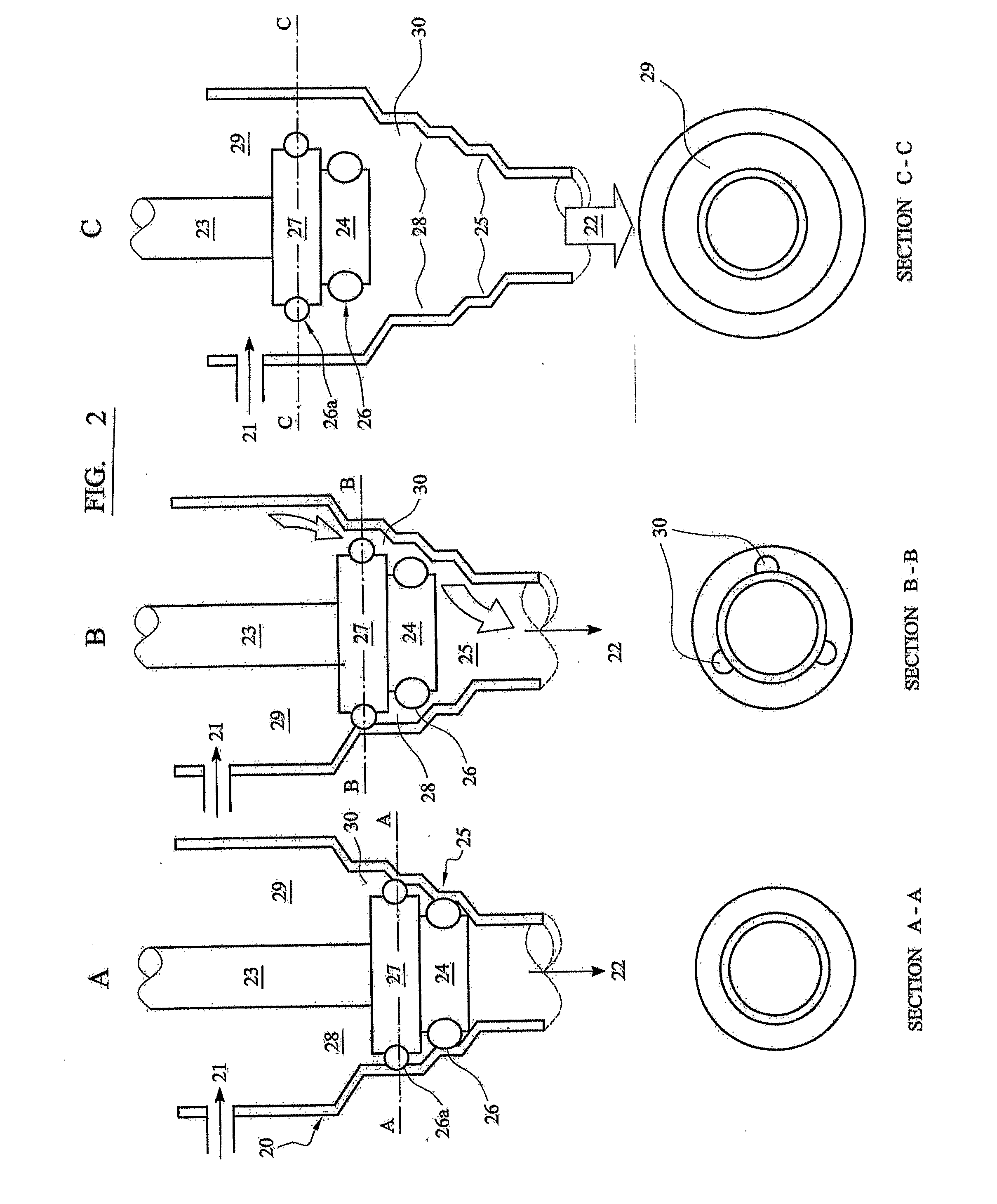
[0032]When piston 23 begins to withdraw, flow through channels 30 is opened in position B (see end section view B-B). This is equivalent to FIG. 2.
[0033]Position C is a fully open flow mode past the stepped zones of main body 20 toward outlet 22.
third embodiment
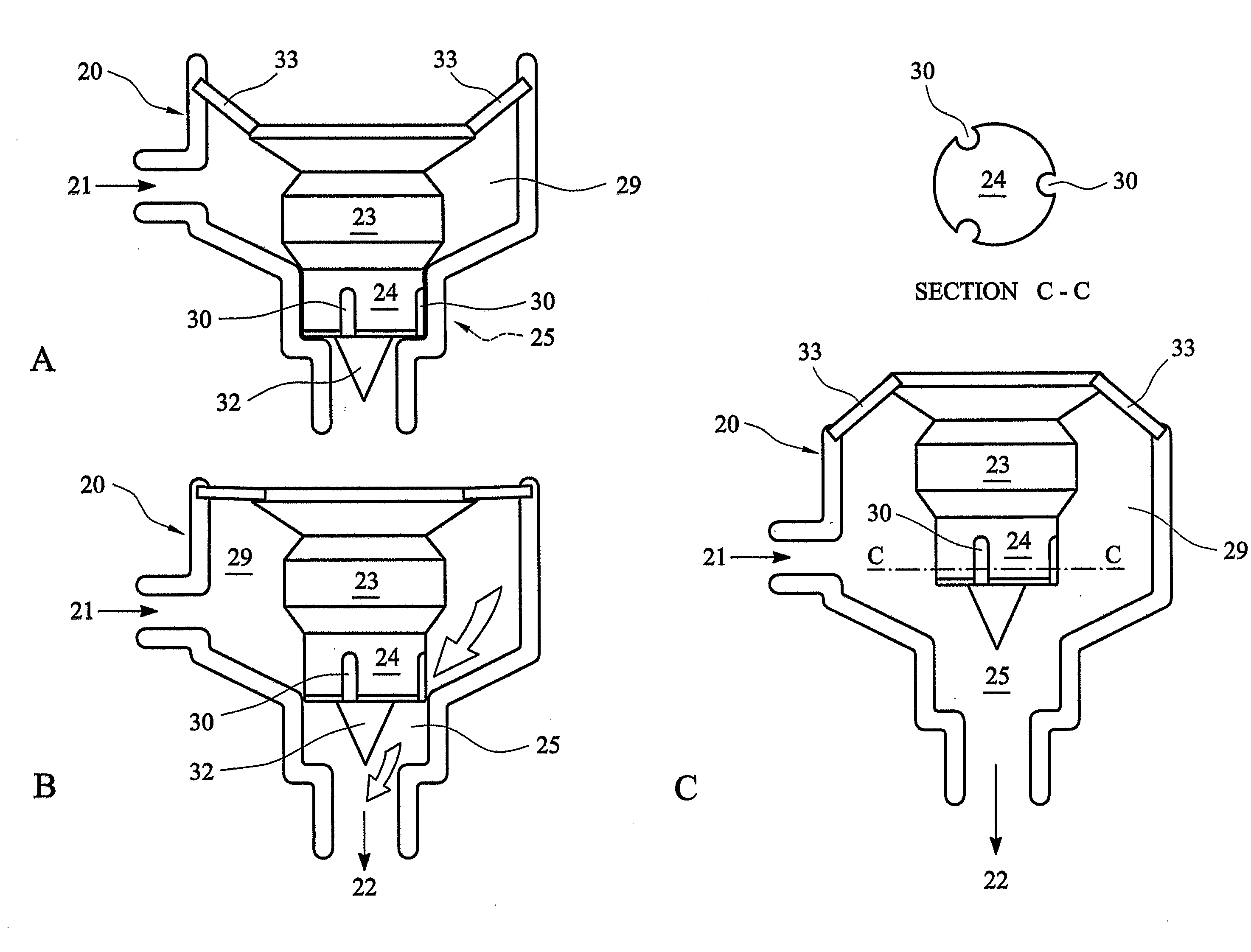
[0034]FIG. 4 illustrates a third embodiment with the same three-stage operation, but where the channels 30 are provided longitudinally in the wall of piston head 24 and not in the main body 20.
[0035]As can be seen in position A, the channels 30 extend from a lower-most edge of piston head 24 to a length terminating before zone 25 widens to zone 29 (there is no need for second zone 28 in FIG. 4). As such, turbulent flow begins when the piston 23 is withdrawn to a point where the channels 30 rise above zone 25 (position B). A conical end 32 on piston head 24 directs flow out of outlet 22.
[0036]Position C shows piston 23 withdrawn into zone 29 to open flow fully through the dispenser.
[0037]It will be apparent in FIG. 4 that a diaphragm 33 between an upper end of piston 24 and radially connected with the wall of main body 20 provides a seal to prevent the upper parts of the dispenser (where a lever or other control means would be located) being flooded and / or leaking.
[0038]The reverse m...
fifth embodiment
[0043]A fifth embodiment illustrated by FIG. 6 features channel means 35 formed in an upstream position on piston head 24 (by contrast to FIG. 4 and its more downstream channels 30).
[0044]As usual, position A is fully closed. The piston head 24 is angled in a conical shape with sealing properties against a corresponding sloped surface of main body 20 toward outlet 22. In this embodiment there are not strictly any stepped “zones” as in FIGS. 2 to 5.
[0045]As piston 23 withdraws, flow is opened to outlet 22. In this case flow at position B is fully open to deliver fluid.
[0046]As piston 23 continues to withdraw it contacts an annular insert 36 with a central bore passage that prevents further upward movement of piston head 24. Insert 36 is located around the tubular wall of main body 20 and may have conically inward-sloped walls to conform and seal with an upper surface of piston head 24. Insert 36 would close flow through the dispenser completely, however, channels 35 in the upper surf...
PUM
 Abstract
Description
Claims
Application Information