Crystalliser Holding Device

a technology of holding device and crystalliser, which is applied in the direction of melt holding vessel, casting apparatus, manufacturing tools, etc., can solve the problems of inconvenient operation of replacing crystalliser, inability to change the format of the product to be cast, and complicating both the crystalliser holding device and the crystalliser changing operation, so as to achieve high constructive simplicity and reduce the overall weight

Active Publication Date: 2009-01-15
DANIELI & C OFF MEC SPA
View PDF4 Cites 0 Cited by
  • Summary
  • Abstract
  • Description
  • Claims
  • Application Information

AI Technical Summary

Benefits of technology

[0010]The primary purpose of the present invention is to achieve a crystalliser holding device or cartridge, containing a crystalliser for steel billets, blooms and slabs production plants, that has a high constructive simplicity, a significantly reduced overall weight and that reduces substantially to zero the need for maintenance.

Problems solved by technology

A first disadvantage of this casting device is that of providing an introduction of the pressurised fluid into the aforesaid gap, which inevitably entails a deformation of the crystalliser walls under hydraulic thrust.
A further disadvantage is represented by the fact that in the upper distribution chamber the pressurised cooling fluid generates a force that acts also on the upper closing flange, that therefore must be made with a great thickness in order to prevent the deformation thereof under the considerable hydraulic thrust and, furthermore, must be fastened with a considerable number of screws to the support structure.
Furthermore, such a device makes the operation of replacing the crystalliser inconvenient in the case, for example, that the format of the product to be cast has to be changed.
Disadvantageously, this configuration of the cooling fluid feeding circuit is also such as to deform the crystalliser walls and to exert a significant hydraulic thrust on the upper closing flange that must therefore be fastened to the support structure with a high number of screws, which complicates both achievement of the crystalliser holding device and the crystalliser changing operations, and entails high production costs.

Method used


Image

  • Crystalliser Holding Device
  • Crystalliser Holding Device
  • Crystalliser Holding Device

Examples


first embodiment

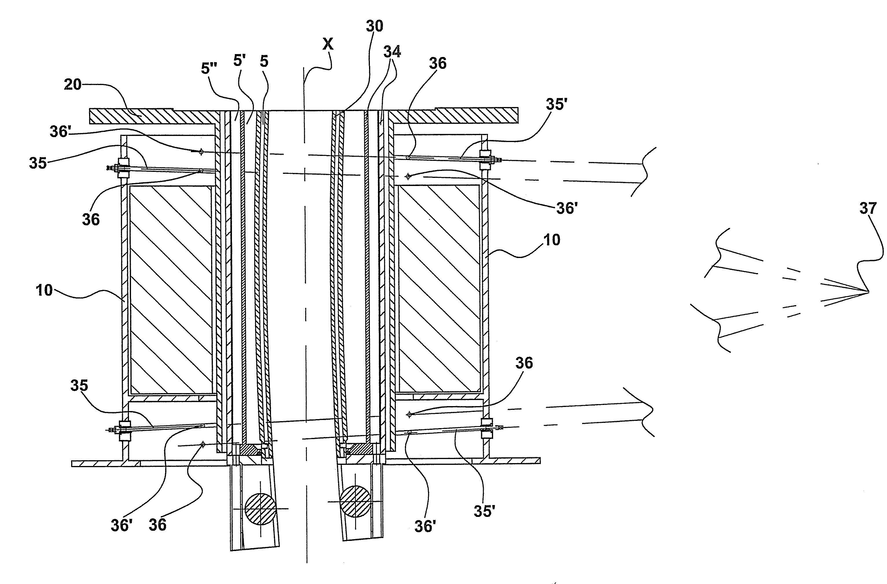
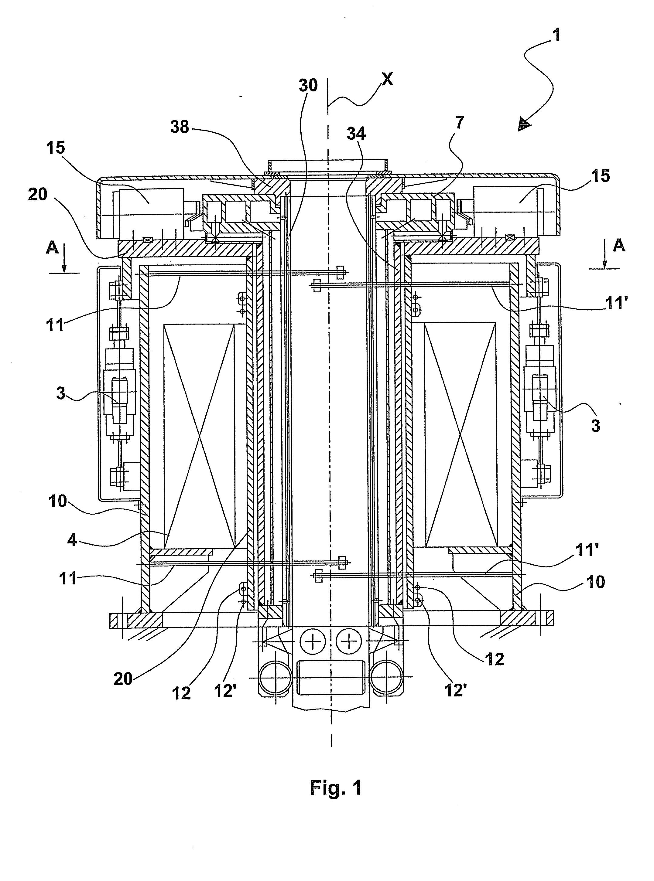
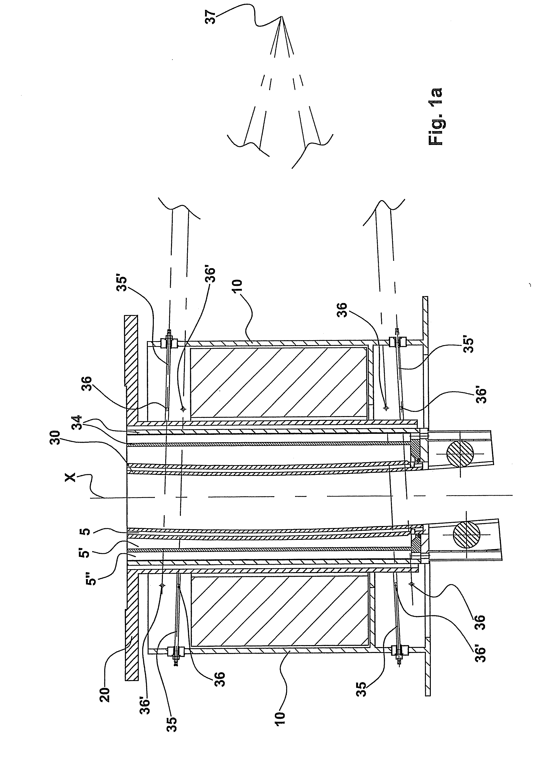
[0030]With reference to FIG. 3, the crystalliser holding device or cartridge of the invention is represented. Such crystalliser holding device 34 houses a tubular crystalliser 30 and is provided with a manifold 7 for feeding and distributing at least one crystalliser cooling fluid.

[0031]Crystalliser 30 and manifold 7 are solidarily joined by an upper closing flange 38. The crystalliser holding device 34 is inserted into an oscillating table support structure 20, suited to being oscillated by an oscillation control comprising for example a pair of hydraulic or mechanical actuation means 3, such as cylinders, provided on an external support structure 10 fixed to the ground.

[0032]The crystalliser holding device 34 comprises a ring-shaped manifold 7 for feeding cooling fluids, obtained by melting or by means of an electrowelded structure, which surrounds the head of the tubular crystalliser 30.

[0033]Advantageously the crystalliser holding device 34 is fixed to the oscillating table than...

second embodiment

[0043]A first variant of this second embodiment, illustrated in FIG. 4a, provides an external manifold 70 fixed to the external support structure 10, fixed to the ground, of an oscillating table in which the crystalliser holding device is housed. In this first variant, the external manifold is constituted by a ring-shaped chamber 70 fed with a pressurised cooling fluid, generally untreated water, by tubes 80. In the internal part thereof, said ring-shaped chamber 70 is provided with a plurality of holes 100, suited to generating jets of said fluid towards the rollers 50 at the foot and the continuous ingot.

[0044]A second variant of this second embodiment, illustrated in FIG. 4b, on the other hand, provides tubes 80′ that feed ring-shaped manifolds 90 that in turn feed spray nozzles 200, arranged in correspondence with the rollers 50 at the foot of the crystalliser 30.

[0045]Advantageously, this second embodiment of the crystalliser holding device in its two variants makes it possible...


PUM

PropertyMeasurementUnit
frequenciesaaaaaaaaaa
thicknessaaaaaaaaaa

Abstract

Crystalliser holding device for billets, blooms and slabs production plants that has a high constructive simplicity, a significantly reduced overall weight and that reduces substantially to zero the need for maintenance. The crystalliser holding device of the invention, in addition to efficaciously guaranteeing the transfer toward the exterior of the heat of the liquid steel introduced into the tubular crystalliser contained therein, also provides a separate circuit for cooling the continuous ingot exiting the crystalliser and the rollers at the foot. It also permits an easy and rapid replacement in the oscillating table in which it is housed.

Description

TECHNICAL FIELD[0001]The present invention refers to a crystalliser holding device, specifically a device suited to housing a crystalliser used in plants for the production of steel billets, blooms and slabs, suited to being fastened in an oscillating table.STATE OF THE ART [0002]The state of the art includes numerous crystalliser holding devices, also known as cartridges, described in different patent documents.[0003]Of these documents, patent GB2156252 describes a continuous casting device comprising a crystalliser inserted inside a crystalliser holding cooling device. This device in turn comprises an upper chamber for the distribution of the pressurised cooling fluid inside a space, or gap, between a crystalliser guiding wall and the crystalliser itself, and a lower cooling fluid return chamber. There are provided relative ducts for the entry of the fluid into the upper chamber and for the exit of the fluid from the lower chamber.[0004]A first disadvantage of this casting device ...

Claims


Application Information

Patent Timeline
Patent Type & Authority Applications(United States)
IPC IPC(8): B22D30/00
CPCB22D11/053B22D11/124B22D11/055
Inventor POLONI, ALFREDODE LUCA, ANDREAANSOLDI, MARCO
Owner DANIELI & C OFF MEC SPA
Why Eureka
Try Eureka