Miniaturized generator with oscillating magnets for the production of electric energy from vibrations

a technology of electric energy and oscillating magnets, applied in the direction of dynamo-electric components, dynamo-electric machines, electrical apparatus, etc., can solve the problems of reducing efficiency, limiting the possibility of miniaturization, increasing the weight and bulk of devices, etc., and achieves the effect of greater miniaturization

Active Publication Date: 2011-07-28
PIRELLI TYRE SPA
View PDF7 Cites 1 Cited by
  • Summary
  • Abstract
  • Description
  • Claims
  • Application Information

AI Technical Summary

Benefits of technology

[0010]A particular object of the present invention is to provide a generator of the aforementioned type which allows the energy which can be extracted from a vibrating support to be maximized.
[0011]Another object of the present invention is to provide a generator of the aforementioned type by which friction losses, contact wearing and seizure risks are minimized.
[0012]A further object of the present invention is to provide a generator of the aforementioned type which has a high constructive simplicity associated with a structure having good tolerance to particulate matter.

Problems solved by technology

The circuit in ferromagnetic material increases the weight and the bulk of the device and limits the possibility of miniaturization.
Moreover, the presence of a substantial volume of ferromagnetic material, with respect to the volume of the entire device, causes a decreasing of the efficiency due to magnetic hysteresis cycle of the ferromagnetic material and to energy dispersion associated with the parasitic currents induced therein.
The aforementioned generators have structural characteristics that limit the possibility of miniaturizing them: for example, due to their intrinsic bulk, it is not possible to make an optimal arrangement of the electronic components inside them; the presence of the ferromagnetic cores has a negative impact upon their weight, on their efficiency, as well as on their constructive simplicity.

Method used


Image

  • Miniaturized generator with oscillating magnets for the production of electric energy from vibrations
  • Miniaturized generator with oscillating magnets for the production of electric energy from vibrations
  • Miniaturized generator with oscillating magnets for the production of electric energy from vibrations

Examples


Embodiment Construction

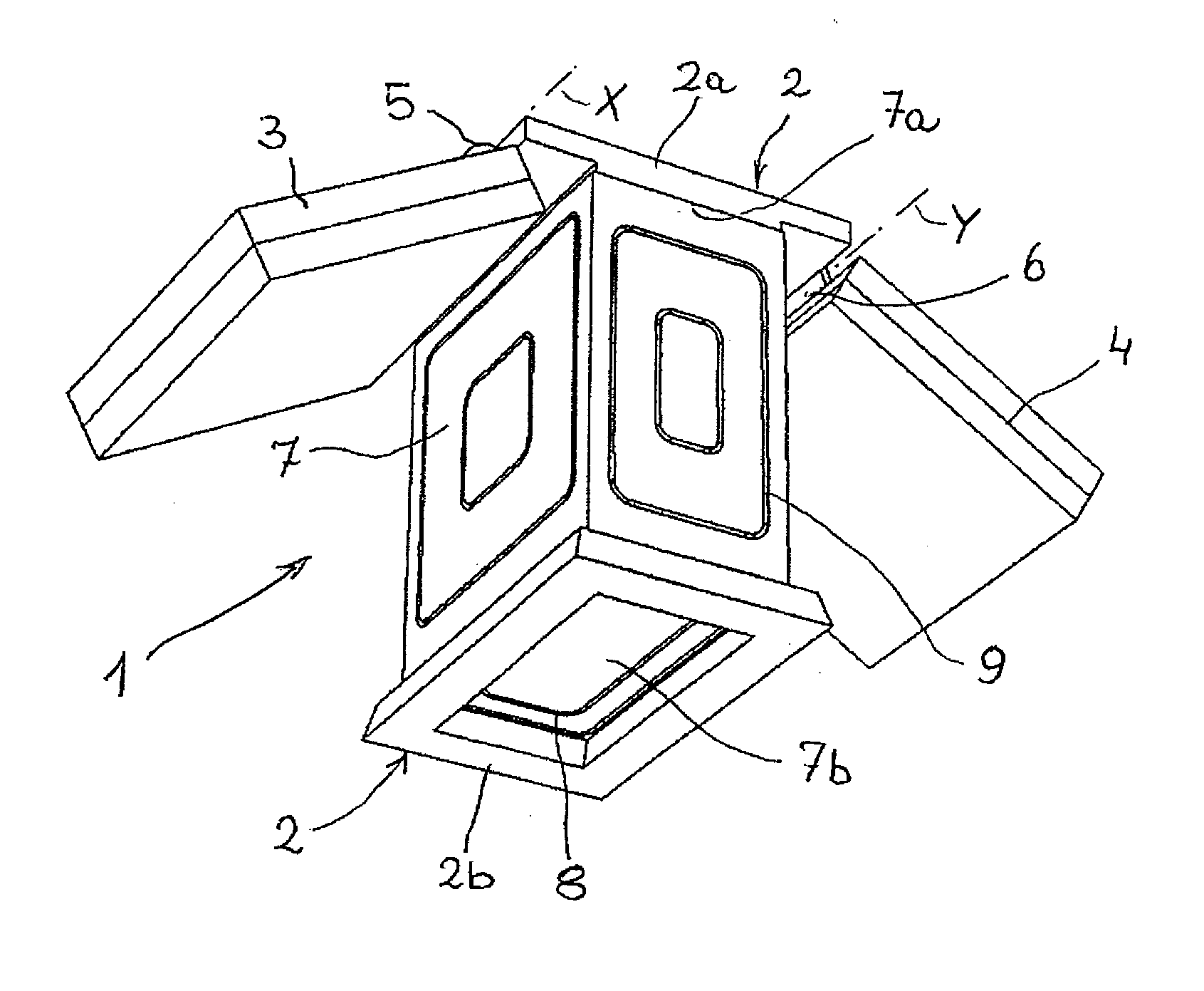
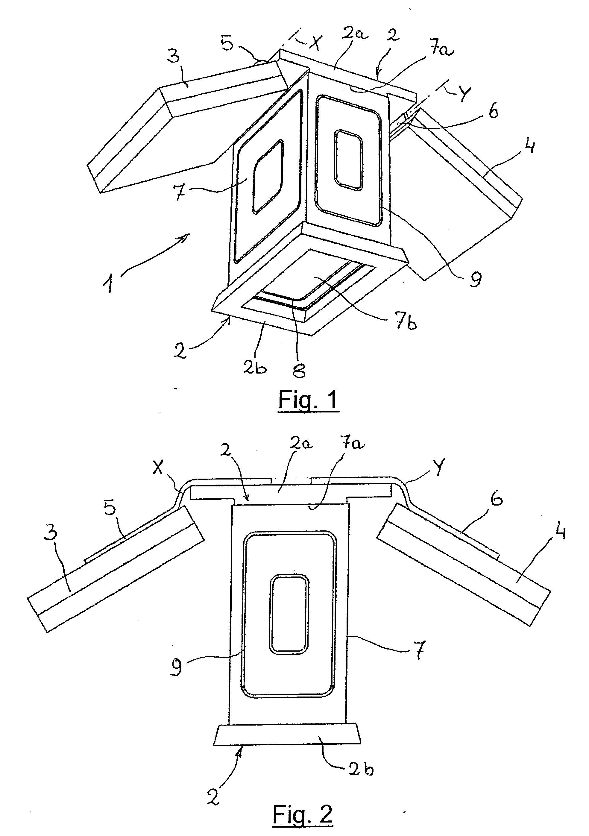
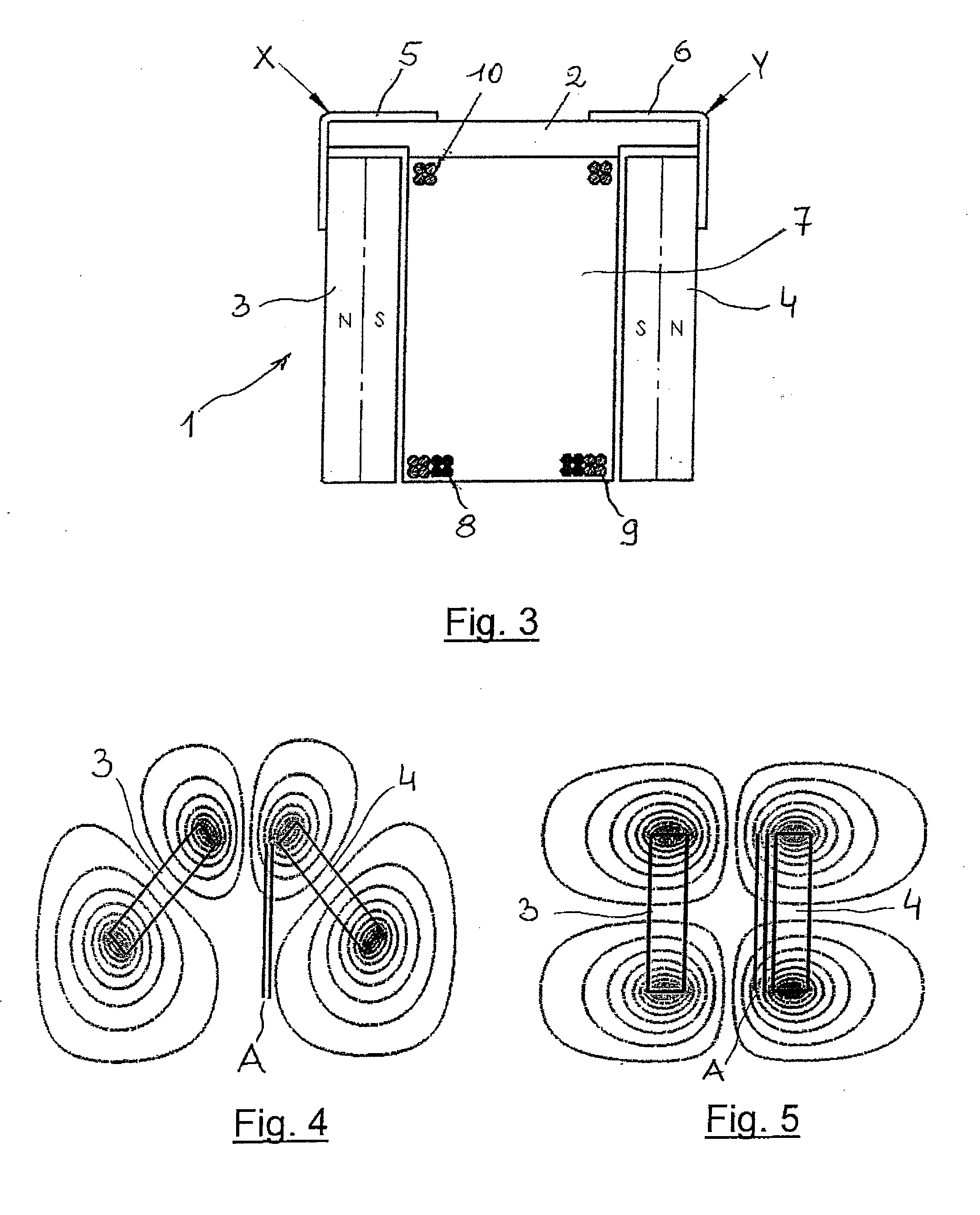
[0022]With reference to FIGS. 1, 2 and 3, an electric energy generator from vibrations is illustrated generally indicated with reference numeral 1. The generator 1 comprises a frame 2 for connecting the generator to a vibrating base, not shown, a central body 7, made from non-ferromagnetic material, for example plastic, rigidly connected to the frame 2 and a pair of permanent magnets 3 and 4 connected to the frame 2 through respective rotational members 5 and 6 having a hinge function.

[0023]In the embodiment illustrated in the mentioned figures, the frame 2 is formed by two frame portions indicated by 2a and 2b connected to opposite sides of the central body 7, said frame portions being defined as upper and lower frame portions, the terms “upper” and “lower” exclusively referring to the position of the frame portions in the attached drawings. The two magnets 3 and 4 are connected to the upper frame portion 2a through the rotational members 5 and 6. The lower frame portion 2b is subs...


PUM


Abstract

An electric energy generator from a vibrational field includes a body of non-ferromagnetic material, at least one pair of permanent magnets pivotally hung from the body in such a way that they are arranged therebetween. The magnets have faces of equal magnetic polarity turned to each other from opposite sides of the body, whereby a repulsive force is established between the magnets tending to keep them spread apart in an equilibrium position. A plurality of electric coils is arranged on the surface of the body so as to intercept the magnetic field generated by the magnets. The body is configured to be connectable to a vibration source, the vibration contrasting the repulsive force and causing an oscillation of the magnets about the equilibrium position, thereby generating a magnetic flux variation and thus an electric power production as an output from the electric coils.

Description

FIELD OF THE INVENTION[0001]The invention relates generally to the field of energy generation, in particular through recovery from sources available in the environment. More precisely, the invention concerns a miniaturized generator with oscillating magnets for the production of electric energy from vibrations.BACKGROUND ART[0002]Most of the devices developed to this day for the recovery of vibrational energy use a mobile mass connected to an elastic element that, once excited, begins to oscillate. This oscillation movement allows electric current to be generated in two ways:[0003]through a piezoelectric generator (see, for example, patents FR2838885 and JP2005335692),[0004]through induction, by coupling the oscillating mass, featured by suitable magnetic properties, with a fixed coil (see for example, U.S. Pat. No. 7,009,315).[0005]In U.S. Pat. No. 7,009,315, for example, vibration is applied to a copper coil and is transmitted through a spring to a magnet causing a relative moveme...

Claims


Application Information

Patent Timeline
Patent Type & Authority Applications(United States)
IPC IPC(8): F03G7/08
CPCH02K35/02
Inventor STEFANINI, CESARECASTRATARO, PIEROACCOTO, DINO
Owner PIRELLI TYRE SPA
Why Eureka
Try Eureka