
Vehicle Seat Comprising an Air Conditioning Unit

a technology for vehicle seats and air conditioners, which is applied in the direction of chairs, transportation and packaging, vehicle arrangements, etc., can solve the problems of cost-effective insertion of flow channels into the surface of seat pans and/or the dispensing of backrest upholstery, and achieve the effect of improving the structural design of the air-conditioning of the vehicle sea

Inactive Publication Date: 2009-01-15
BROSE FAHRZEUGTEILE GMBH & CO KG
View PDF13 Cites 25 Cited by
  • Summary
  • Abstract
  • Description
  • Claims
  • Application Information

AI Technical Summary

Benefits of technology

[0003]The object of the invention is to improve structurally the design of the air-conditioning of a vehicle seat.
[0004]To this end, a fan receptacle and at least one flow channel are molded into the seat pan and / or into the backrest. In this manner, a retrospective insertion of the fan receptacle into the seat pan and / or backrest configured in the manner of a shell is not necessary for attaching the fan. Moreover, the costly insertion of the flow channels into the surface of the seat pan and / or backrest upholstery is dispensed with. Instead, the seat pan and / or the backrest may be provided with conventional upholstery. The air conditioning unit is, therefore, able to be designed considerably more cost-effectively relative to an air conditioning unit according to the prior art.
[0005]In an expedient development, the fan receptacle forms a housing for a fan wheel associated with the fan. In this manner, the costs for the housing of the fan may be completely saved. Moreover, a finishing step is dispensed with, as the fan wheel is now directly inserted into the fan receptacle. An insertion of the fan wheel into a corresponding housing and a subsequent mounting of the fan with its housing onto the fan receptacle is no longer necessary.
[0009]The air distribution element is advantageously designed as a profiled cushion or as an air distribution mat. The cushion may be provided in a simple manner with such a profiled surface. In a simple manner, therefore, flow channels are formed by the cushion cover on the surface of the upholstery, which distribute the conveyed air on the surface of the upholstery.
[0012]In an advantageous development, the flow channel comprises supporting contours facing the upholstery and is designed to be open towards the upholstery. In other words, the flow channel is only sealed and completed by the upholstery inserted into the seat pan and / or into the backrest. By the provision of supporting contours, it is possible to influence how far the upholstery is pressed in by the body weight of a person sitting on the vehicle seat and how far, therefore, the flow cross section of the flow channel is reduced. By a suitable support of the upholstery, it may thus be able to be achieved that even with a person with a high body weight, a sufficient flow cross section is maintained for the flow of air onto the air distribution element. Moreover, the seat pan and / or the backrest may be produced in one piece without undercuts and thus easily removed from the mold. Thus the simple manufacture of the seat pan and / or backrest is possible as a plastics injection-molded part. For securing the structure of the seat pan and / or backrest the plastics may be designed to be glass fiber-reinforced. As a result of this one-piece design and the comparatively simple component geometry, the air conditioning unit may be integrated in a simple and cost-effective manner into the vehicle seat.

Problems solved by technology

Moreover, the costly insertion of the flow channels into the surface of the seat pan and / or backrest upholstery is dispensed with.

Method used


Image

  • Vehicle Seat Comprising an Air Conditioning Unit
  • Vehicle Seat Comprising an Air Conditioning Unit
  • Vehicle Seat Comprising an Air Conditioning Unit

Examples


Embodiment Construction

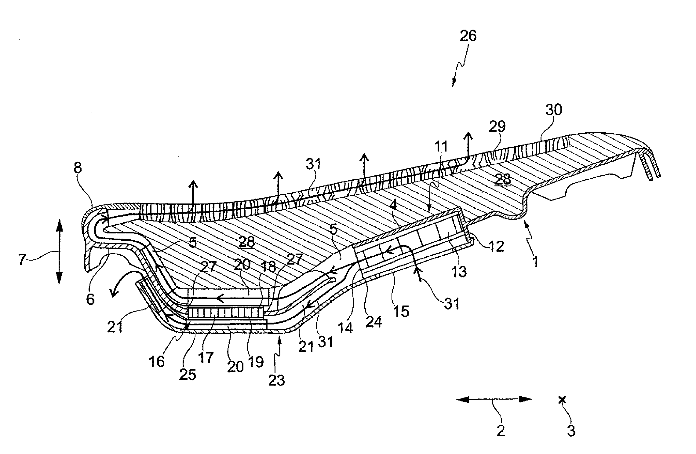
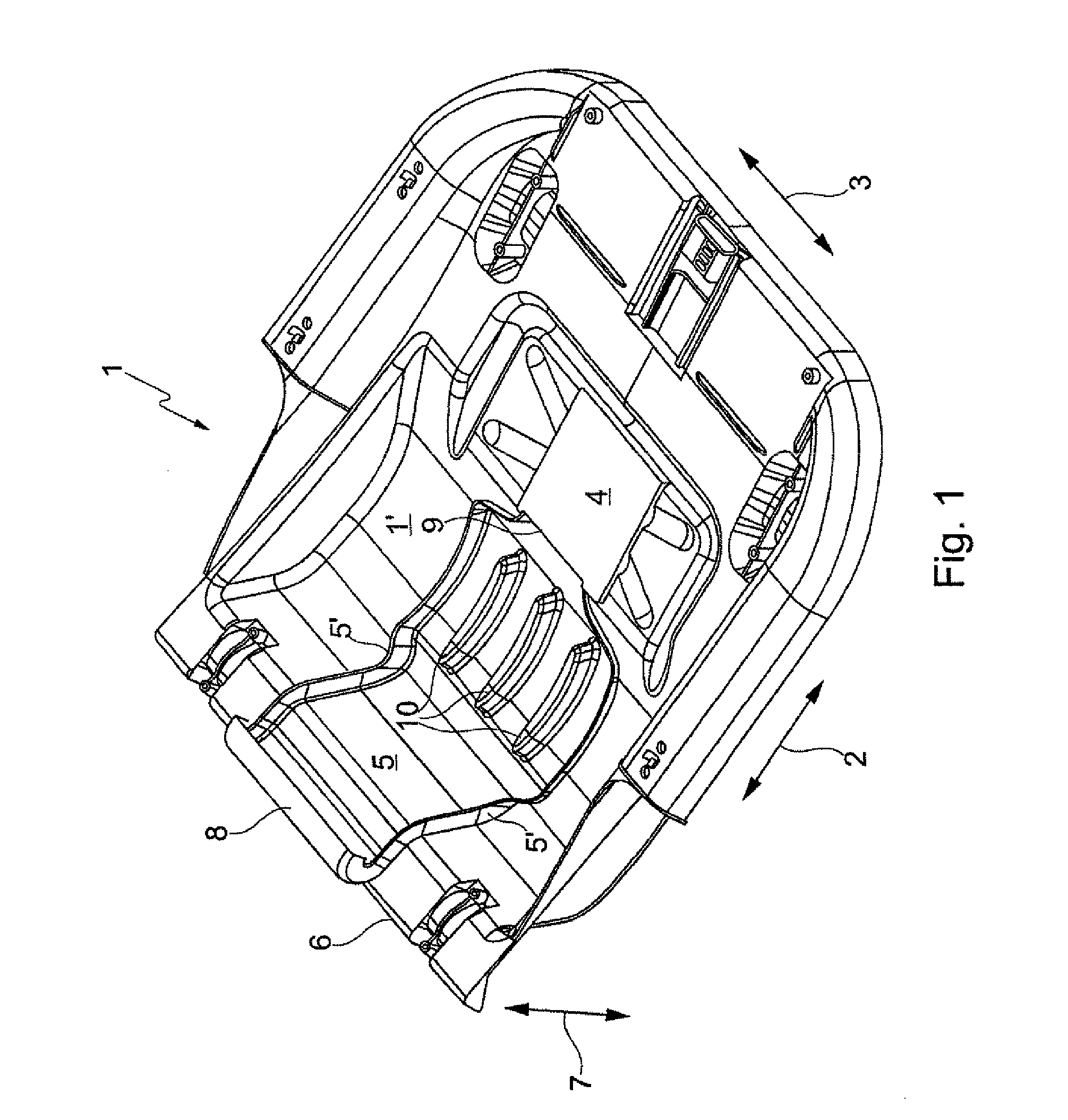
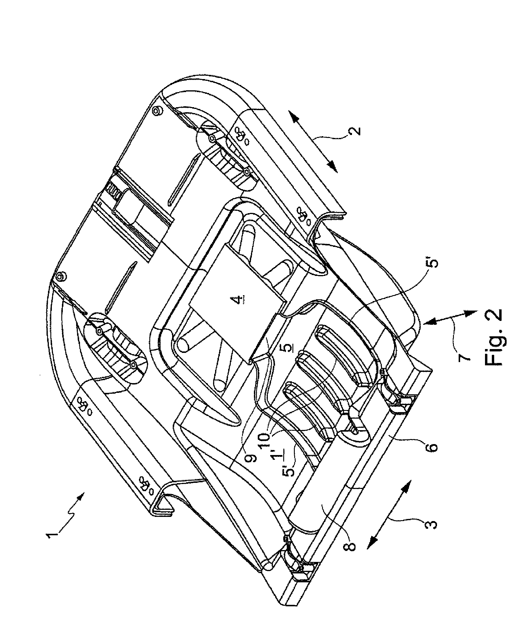
[0027]FIG. 1 shows a first seat pan 1 of a motor vehicle seat, not shown in the figures. The seat pan 1 is designed in the manner of a trough for receiving seat pan upholstery, not shown in this and the following figures. It is made in one piece as a glass fiber-reinforced plastics injection-molded part. Viewed in the center from its longitudinal direction 2 corresponding to the motor vehicle longitudinal direction in the final assembled state and the transverse direction 3, the seat pan 1 has a fan receptacle 4 of plate-shaped design. Two channel walls 5′ extending in the longitudinal direction 2 and projecting from the surface 1′ of the seat pan are formed away from the fan receptacle 4 for forming a flow channel 5. The channel walls 5′ and thus the flow channel 5 extend as far as the seat pan edge 6. As may be derived from FIG. 1, the flow channel 5 extends away from the fan receptacle 4, initially substantially in the longitudinal direction 2 and then in the vertical direction 7...


PUM


Abstract

The vehicle seat comprises an air conditioning unit associated with the seat pan and / or the backrest. The air conditioning unit comprises a fan, a flow channel and an air distribution element arranged on the upper face of the seat pan and / or backrest upholstery and connected to the fan via the flow channel. A fan receptacle and the flow channel are molded into the seat pan and / or into the backrest.

Description

FIELD OF THE INVENTION[0001]The invention relates to a vehicle seat comprising an air conditioning unit associated with the seat pan and / or the backrest. The air conditioning unit comprises a fan, a flow channel and an air distribution element arranged on the upper face of the seat pan and / or the backrest upholstery and connected to the fan via the flow channel.BACKGROUND OF THE INVENTION[0002]Such an air conditioning unit for a vehicle seat is known from DE 103 16 275 A1. The seat pan and the backrest of the vehicle seat are formed in a shell-like manner. The seat pan is configured for receiving the seat pan upholstery and the backrest is configured for receiving the backrest upholstery. The seat pan and the backrest upholstery have on their upper face a plurality of flow channels connected to one another and incorporated in the upholstery. At the same time, the flow channels of the seat pan upholstery and the flow channels of the backrest upholstery merge with one another. The flo...

Claims


Application Information

Patent Timeline
Patent Type & Authority Applications(United States)
IPC IPC(8): B60N2/56A47C7/74A47C31/00
CPCB60H1/00285B60H1/00564B60N2/5657B60N2/5635B60H2001/003B60N2/686B60N2/5642
Inventor MACHT, ALWINSTEGNER, DANIELABROSIUS, STEFFEN
Owner BROSE FAHRZEUGTEILE GMBH & CO KG
Learn More