Piezoelectric electroacoustic transducer

a technology of electroacoustic transducers and diaphragms, applied in piezoelectric/electrostrictive/magnetostrictive devices, electrical transducers, piezoelectric/electrostriction/magnetostriction machines, etc., can solve problems such as and achieve the effect of preventing excessive curvature of piezoelectric diaphragms and preventing cracking of conductive adhesives

Active Publication Date: 2009-01-15
MURATA MFG CO LTD
View PDF13 Cites 31 Cited by
  • Summary
  • Abstract
  • Description
  • Claims
  • Application Information

AI Technical Summary

Benefits of technology

[0016]To overcome the problems described above, preferred embodiments of the present invention provide a piezoelectric electroacoustic transducer that prevents an excessive curvature of a piezoelectric diaphragm due to, for example, an impact, so as to prevent the cracking of a conductive adhesive.

Problems solved by technology

However, an impact can bend the piezoelectric diaphragm with a large curvature and thus crack the conductive adhesive, which connects the electrodes of the piezoelectric diaphragm to the inner connection portions of the terminals.

Method used


Image

  • Piezoelectric electroacoustic transducer
  • Piezoelectric electroacoustic transducer
  • Piezoelectric electroacoustic transducer

Examples


first preferred embodiment

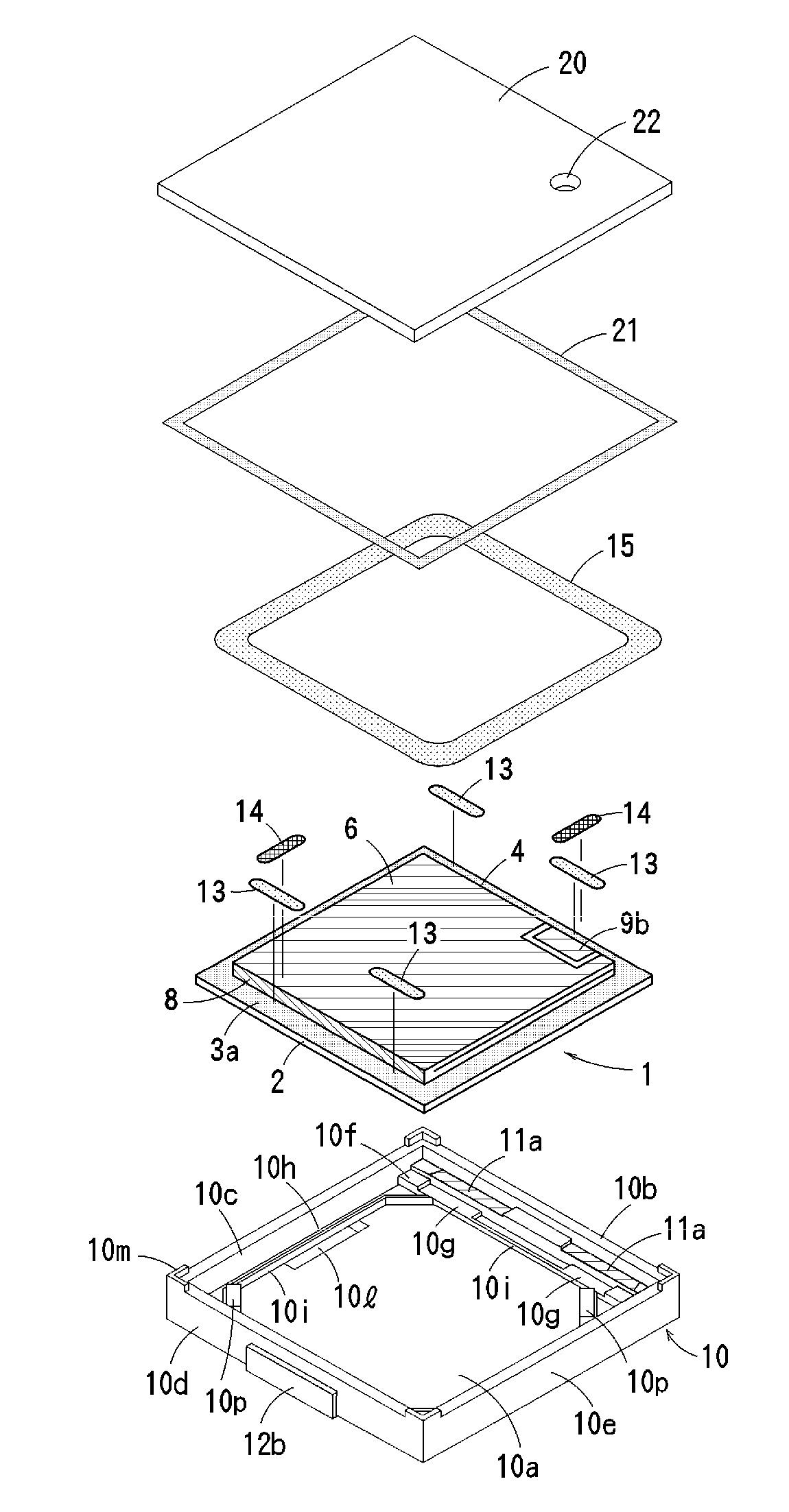
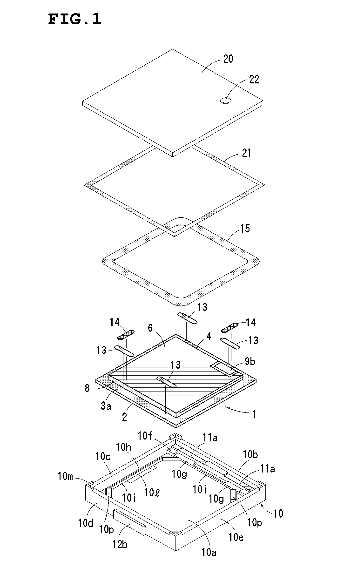
[0046]FIG. 1 illustrates a piezoelectric sounder as an example of a surface-mount piezoelectric electroacoustic transducer according to preferred embodiments of the present invention.

[0047]This piezoelectric sounder primarily includes a piezoelectric diaphragm 1, a case 10, and a cover 20. The case 10 and the cover 20 define a casing.

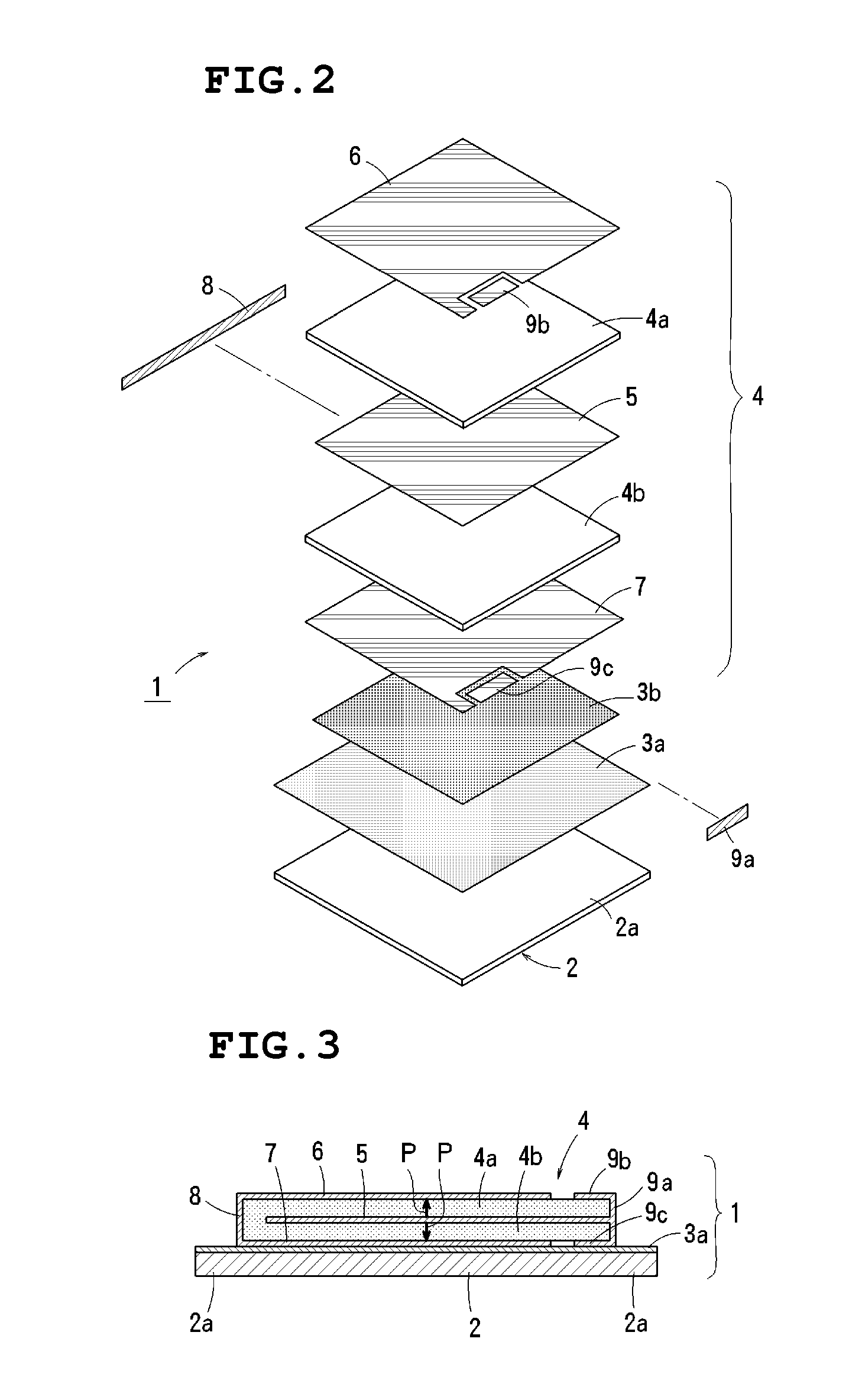
[0048]Referring to FIGS. 2 and 3, the piezoelectric diaphragm 1 in this preferred embodiment includes a substantially square metal plate 2, an insulating layer 3a provided over a surface of the metal plate 2, and a substantially square piezoelectric element 4 bonded and fixed onto the insulating layer 3a. The piezoelectric element 4 is smaller than the metal plate 2. The metal plate 2 is preferably made of a material with spring elasticity, such as phosphor bronze and 42Ni alloy. The insulating layer 3a may be formed of a coating of resin, such as polyimide and epoxy, or an oxide film formed by oxidation.

[0049]The piezoelectric element 4 includes two pi...


PUM


Abstract

A piezoelectric electroacoustic transducer includes a substantially rectangular piezoelectric diaphragm, a case having supports to support the four corners of the bottom surface of the piezoelectric diaphragm, terminals fixed to the case, each including an inner connection portion exposed near the supports, a first elastic adhesive disposed between the periphery of the piezoelectric diaphragm and the terminals, a conductive adhesive disposed between electrodes of the piezoelectric diaphragm and the terminals across the top surface of the first elastic adhesive, a second elastic adhesive filling and sealing a gap between the periphery of the piezoelectric diaphragm and an inner portion of the case, and an overamplitude-preventing receiver provided on a bottom wall of the case to limit the amplitude of vibration of the piezoelectric diaphragm to a predetermined range. The overamplitude-preventing receiver is disposed closer to the center of the piezoelectric diaphragm than the supports.

Description

BACKGROUND OF THE INVENTION[0001]1. Field of the Invention[0002]The present invention relates to piezoelectric electroacoustic transducers such as piezoelectric sounders, piezoelectric receivers, and piezoelectric speakers.[0003]2. Description of the Related Art[0004]Piezoelectric electroacoustic transducers for emitting warning sounds or operating sounds have been widely used in electronic devices, consumer products, and cellular phones, for example, as piezoelectric sounders or piezoelectric receivers. Piezoelectric electroacoustic transducers incorporating a rectangular diaphragm have been proposed to achieve higher production efficiency, higher electroacoustic conversion efficiency, and size reduction.[0005]Extremely thin diaphragms, on the order of tens to hundreds of micrometers in thickness, have recently been used for lower frequencies. The frequency characteristics of such thin diaphragms are greatly affected by the structures that support the diaphragms.[0006]If, for examp...

Claims


Application Information

Patent Timeline
Patent Type & Authority Applications(United States)
IPC IPC(8): H01L41/053H04R17/00
CPCH04R17/00
Inventor ISHIMASA, MITSUNORIKAMI, KEIICHI
Owner MURATA MFG CO LTD
Why Eureka
Try Eureka