Tamper detector for a security sensor

Inactive Publication Date: 2009-01-15
ROBERT BOSCH CORP +1
View PDF13 Cites 14 Cited by
  • Summary
  • Abstract
  • Description
  • Claims
  • Application Information

AI Technical Summary

Benefits of technology

[0016]An advantage of the present invention is that it is difficult for a would-be intruder to defeat the security sensor. Because removal of the security sensor from its mounting would be detected, the would-be intruder may be forced to attempt to defeat the sensor while the sensor is properly mounted.
[0017]Another advantage is that the tamper detector itself is difficult to defeat. Because the optical emitter and receiver of the tamper detector are embedded in the mounting surface, it would be difficult to prevent a change the state of reception of the optical energy by the receiver while, at the same time, removing the security sensor from the mounting surface. More particularly, in embodiments in which the receiver is

Problems solved by technology

A problem with many of these types of security sensors is that it is possible for an intruder to defeat th

Method used


Image

  • Tamper detector for a security sensor
  • Tamper detector for a security sensor
  • Tamper detector for a security sensor

Examples


Example

[0031]Corresponding reference characters indicate corresponding parts throughout the several views. Although the exemplification set out herein illustrates embodiments of the invention, in several forms, the embodiments disclosed below are not intended to be exhaustive or to be construed as limiting the scope of the invention to the precise forms disclosed.

DESCRIPTION OF THE PRESENT INVENTION

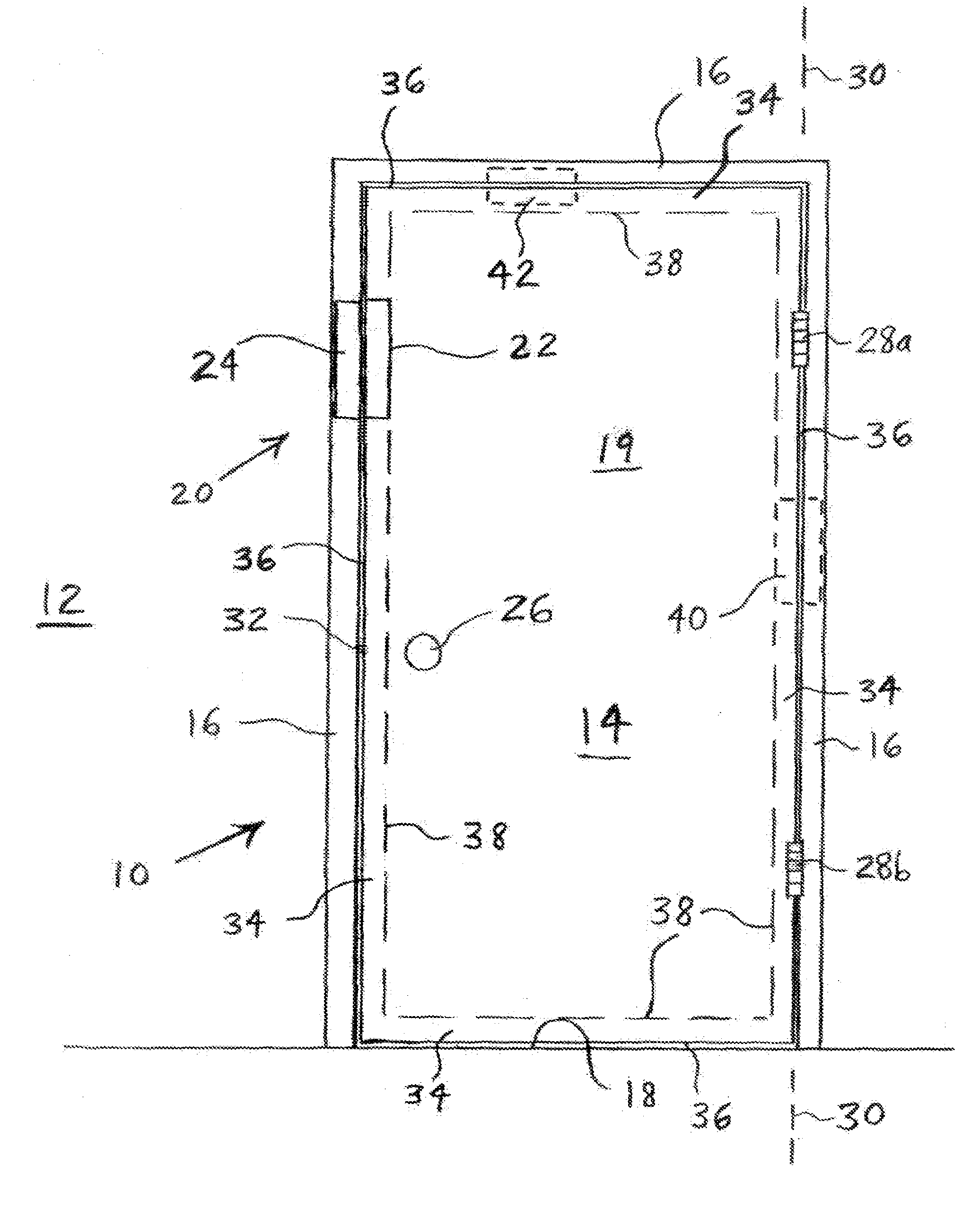
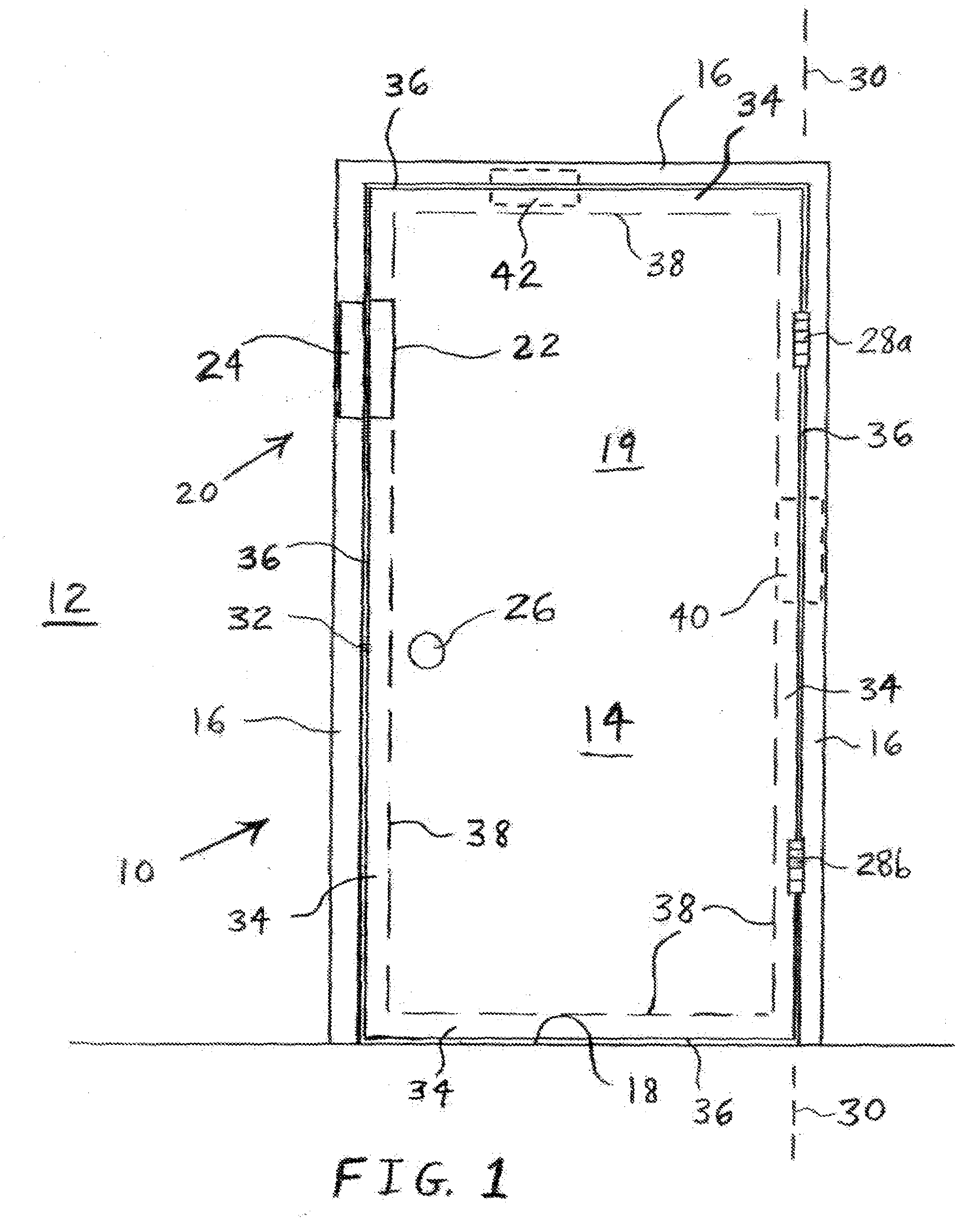
[0032]Referring now to the drawings and particularly to FIG. 1, there is shown one embodiment of a security assembly, in particular a door assembly 10, of the present invention for incorporation into a structure 12 such as a building, or, more particularly, a wall of a building. Door assembly 10 includes a movable building structure in the form of a door 14, which is surrounded by portions of structure 12, such as a door frame 16 and a floor surface 18. Door frame 16 and a floor surface 18 define a building opening 19 in the form of a doorway that door 14 covers when door 14 is in a closed posit...


PUM


Abstract

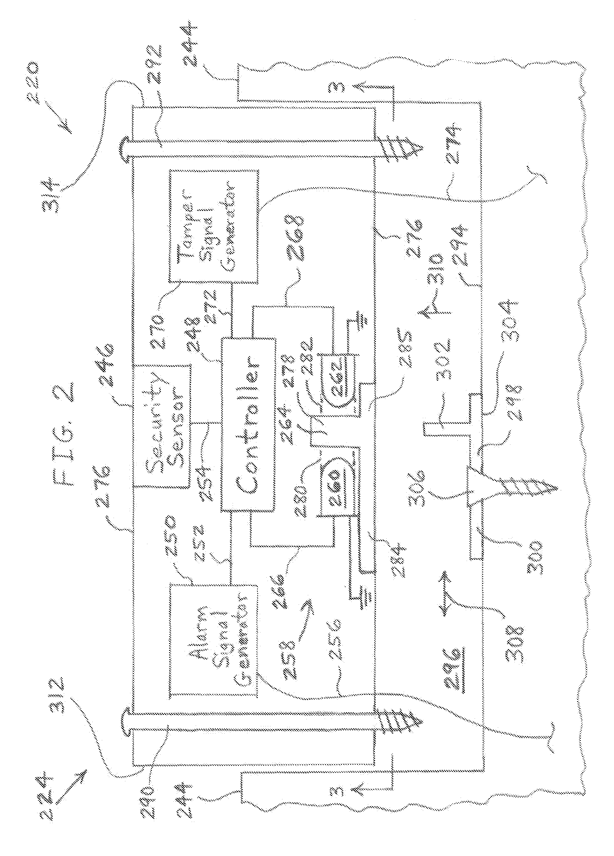
A security arrangement includes a mounting device having an upstanding wall. The mounting device is mounted to a surface of a structure such that the wall is oriented substantially perpendicular to the surface. A security sensor senses an event that occurs outside of the security arrangement. A tamper detector is attached to the security sensor and includes an optical emitter, an optical receiver, and a slot disposed between the emitter and the receiver. The emitter transmits optical energy that is received by the receiver through the slot. The wall of the mounting device is received in the slot when the tamper detector is coupled to the mounting device to thereby block the transmission of the optical energy from the emitter to the receiver. A controller is communicatively coupled to the receiver and produces a tamper signal in response to the receiver receiving the optical energy.

Description

BACKGROUND OF THE INVENTION[0001]1. Field of the Invention[0002]The present invention relates to surveillance system sensors, and, more particularly, to an arrangement for detecting tampering with a surveillance system sensor.[0003]2. Description of the Related Art[0004]Surveillance systems, also known as security systems, are known to include various types of sensors for monitoring a building structure or an area of space for certain phenomena or events, such as a breach of security. For example, the security sensors may include door sensors for detecting the opening and closing of a door, window sensors for detecting the opening and closing of a window, or passive infrared (PIR) sensors for detecting motion or the presence of a living being.[0005]Door / window sensors are known to be in the form of a pushbutton that is mounted to the door / window frame and is held in a depressed state by the door or window when the door or window is in a closed position. When opening, the door or win...

Claims


Application Information

Patent Timeline
IPC IPC(8): G08B13/18
CPCG08B13/08G08B29/046G08B13/186G08B13/183
Inventor DIPOALA, WILLIAM
Owner ROBERT BOSCH CORP
Why Eureka
Try Eureka