Image display apparatus and image display method

a technology of image display and display apparatus, which is applied in the direction of instruments, geometric image transformation, computing, etc., can solve the problems of difficult to see the entire image area, difficult to see displayed information, and part of the image becomes invisibl

Inactive Publication Date: 2009-01-15
CANON KK
View PDF3 Cites 12 Cited by
  • Summary
  • Abstract
  • Description
  • Claims
  • Application Information

AI Technical Summary

Benefits of technology

[0009]The present invention provides an image display apparatus and an image display method which are capable of displaying all the information contained within an image without making it difficult to see the information.
[0012]According to an embodiment of the present invention, a part of an image which extends off a compressed image display area is compressed so that the part fits within the compressed image display area and is displayed on a display screen. Accordingly, all the information contained within the image can be displayed without making it difficult to se the information. As a result, display flexibility can be improved.

Problems solved by technology

However, since the image displayed after a display position has been moved extends off a screen area, a part of the image becomes invisible.
Accordingly, it is difficult to see the entire area of the image.
This makes it difficult to see displayed information.

Method used


Image

  • Image display apparatus and image display method
  • Image display apparatus and image display method
  • Image display apparatus and image display method

Examples


first embodiment

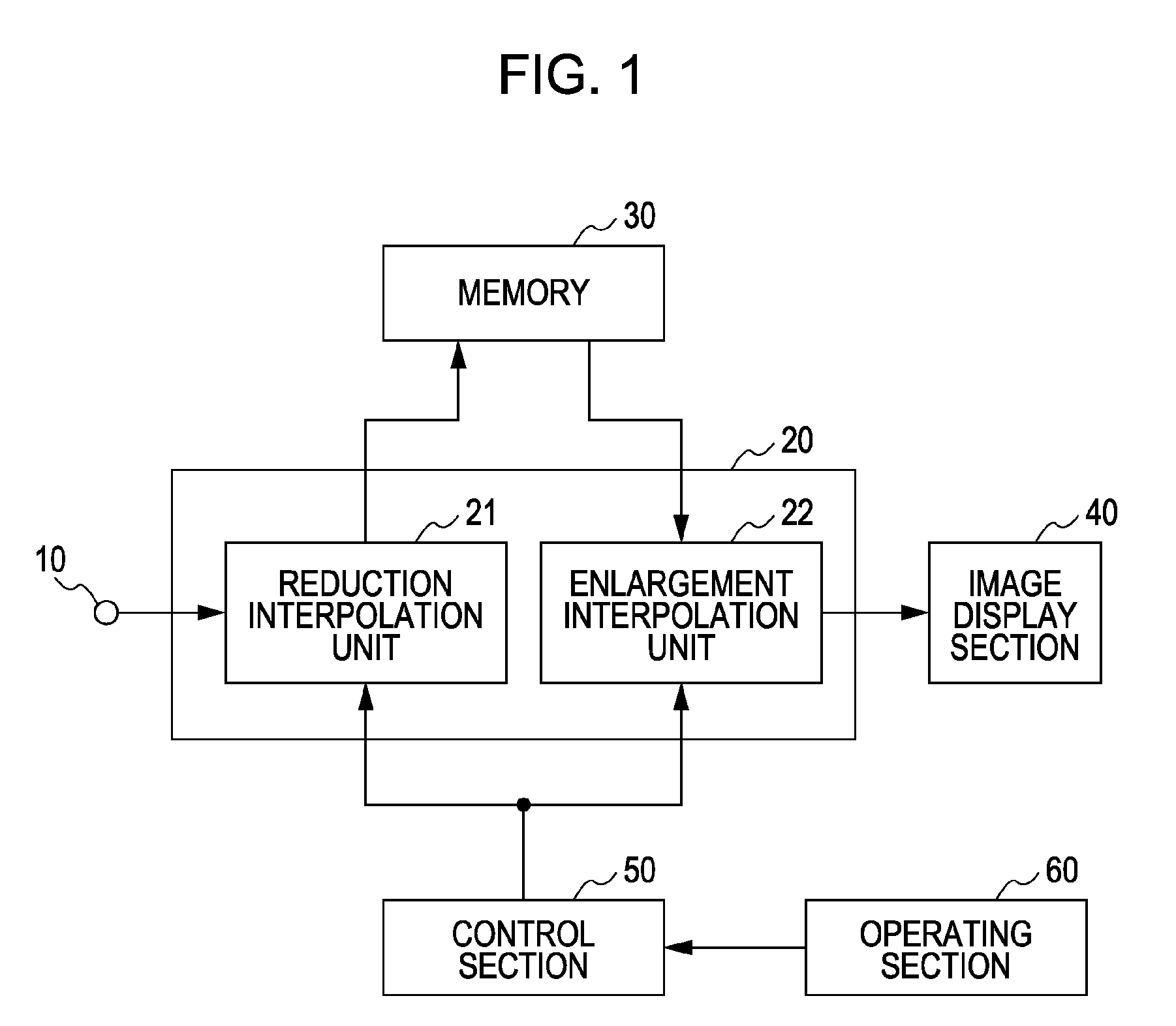
[0037]FIG. 1 is a block diagram schematically illustrating an exemplary configuration of an image display apparatus according to this embodiment. Referring to FIG. 1, an image display apparatus according to this embodiment includes an image signal input section 10, a scaling section 20 for enlarging or reducing an input image, a frame memory 30, an image display section 40 including a display device and a driver for the display device, a control section 50 for controlling an image display apparatus including the scaling section 20, and an operating section 60 for performing a control operation of the image display apparatus. The scaling section 20 includes a reduction interpolation unit 21 and an enlargement interpolation unit 22.

[0038]If an input image is reduced, the reduction interpolation unit 21 performs reduction interpolation processing upon image signals corresponding to an input image by performing predetermined filtering based on a reduction ratio controlled by the control...

second embodiment

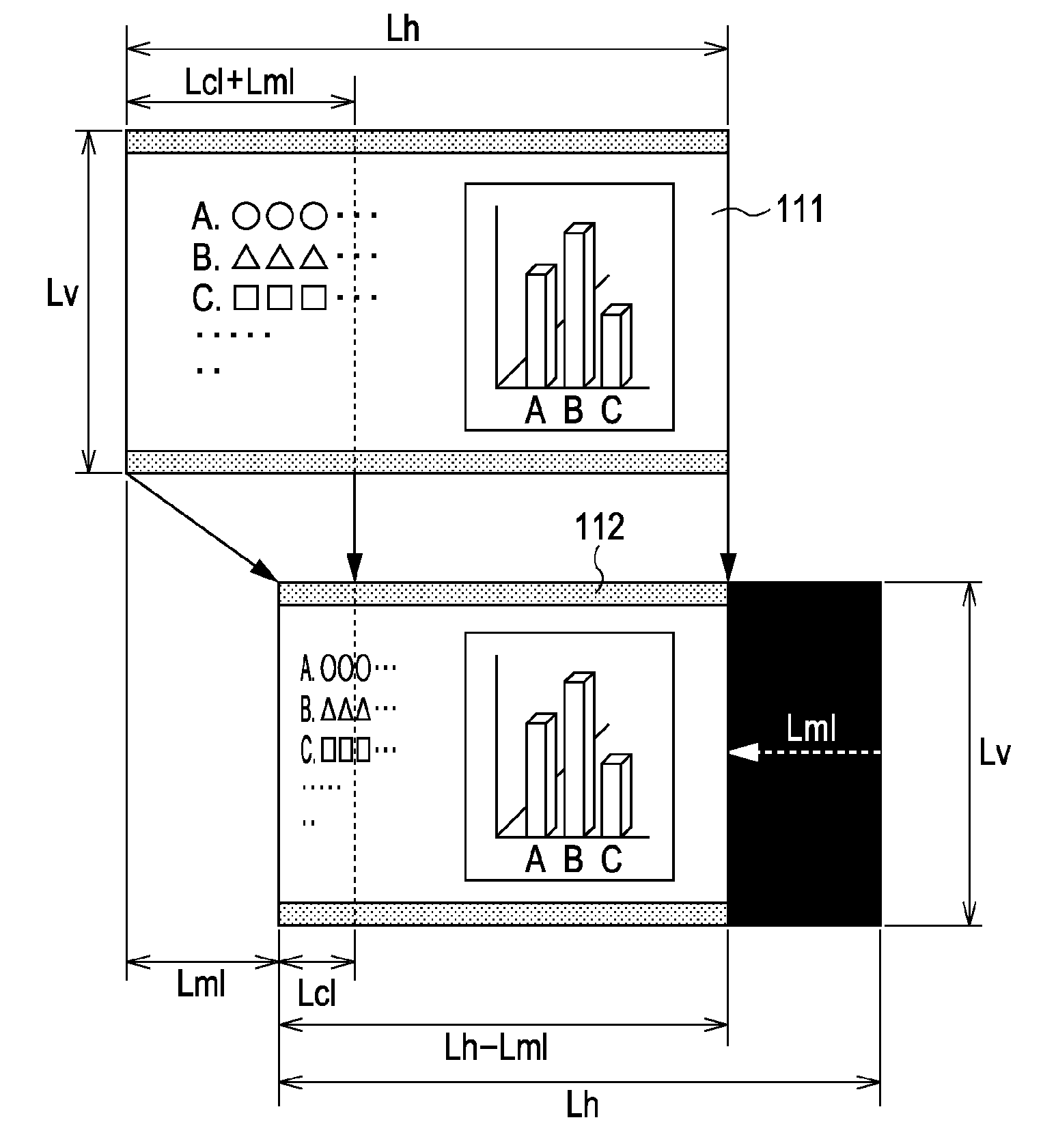
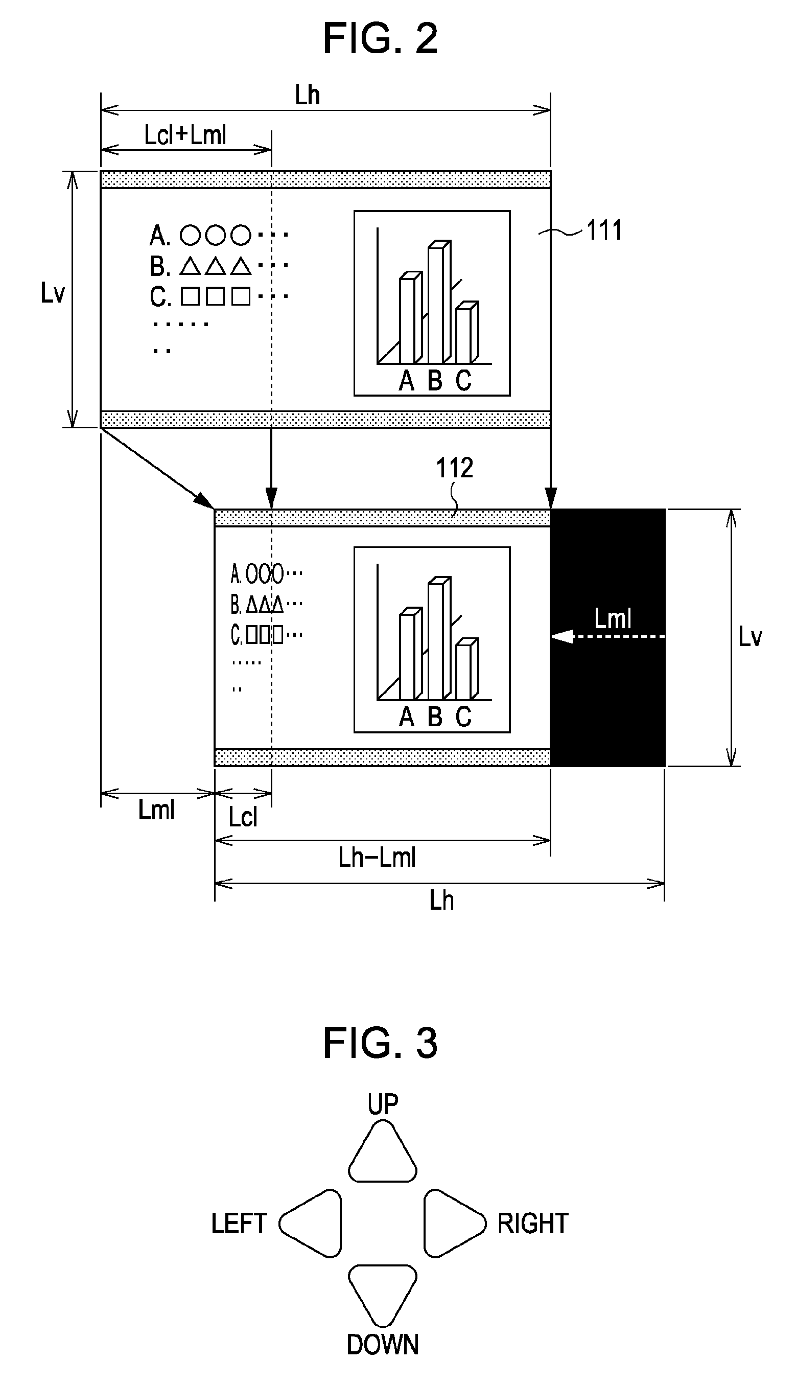
[0056]Next, an example illustrated in FIG. 5 will be described. In this example, on an image display device having Lh pixels in the horizontal direction and Lv pixels in the vertical direction, the image 111 having the same number of pixels as the image display device is input. As illustrated using an image 113, a display position is moved to the right by a distance Lmr in the horizontal direction. The exemplary functional configuration of an image display apparatus according to this embodiment is the same as that of an image display apparatus according to the first embodiment, and the description thereof will be therefore omitted. An area of the image display device from the right end thereof to a position apart from the right end by a distance Lcr in the horizontal direction is set as a compressed image display area.

[0057]In this case, a part of the input image 111 in an area from the right end thereof to a position apart from the right end by a distance (Lcr+Lmr) in the horizonta...

third embodiment

[0065]Next, an example illustrated in FIG. 7 will be described. In this example, on an image display device having Lh pixels in the horizontal direction and Lv pixels in the vertical direction, the image 111 having the same number of pixels as the image display device is input. As illustrated using an image 114, a display position is upwardly moved in the vertical direction by a distance Lmu. The exemplary functional configuration of an image display apparatus according to this embodiment is the same as that of an image display apparatus according to the first embodiment, and the description thereof will be therefore omitted. An area of the image display device from the upper end thereof to a position apart from the upper end by a distance Lcu in the vertical direction is set as a compressed image display area.

[0066]In this case, a part of the input image 111 in an area from the upper end thereof to a position apart from the upper end by a distance (Lcu+Lmu) in the vertical directio...


PUM


Abstract

An image display apparatus according to an embodiment of the present invention includes: a moving unit configured to move a display position of an image displayed on a display screen; a setting unit configured to set a compressed image display area in the image; and a compression unit configured to, when a nondisplay area that is not displayed on the display screen is created in the image by the moving unit, compress the nondisplay area so that the nondisplay area fits within the compressed image display area and is displayed on the display screen.

Description

BACKGROUND OF THE INVENTION[0001]1. Field of the Invention[0002]The present invention relates to an image display apparatus and an image display method, and, more particularly, to a technique for displaying a moved image.[0003]2. Description of the Related Art[0004]In recent years, there have been increased opportunities for displaying data for third parties using a large screen display in a meeting or presentation. For example, various types of data such as textual data, table data, and graphical data, which are created using application software for a personal computer, are displayed for third parties using a large screen display such as a front projector or a rear projector. In such a case, a multi-screen display function of displaying a plurality of images, which are sent from different personal computers or from a personal computer and a video apparatus, at the same time can be effectively used.[0005]The multi-screen display function is used in television sets. As illustrated i...

Claims


Application Information

Patent Timeline
Patent Type & Authority Applications(United States)
IPC IPC(8): G09G5/00G06F3/048
CPCG09G5/00G09G5/14G09G2310/06G09G2340/0414G06T3/40G09G2340/0471G09G2340/0478G09G2360/18G09G2340/0421
Inventor OUCHI, AKIHIRO
Owner CANON KK
Why Eureka
Try Eureka