Image compressor, image expander and image processing apparatus

a technology of image compressor and expander, applied in the field of image compressor and image expander, can solve problems such as the reduction of coding efficiency that occur

Inactive Publication Date: 2009-01-15
KK TOSHIBA
View PDF3 Cites 26 Cited by
  • Summary
  • Abstract
  • Description
  • Claims
  • Application Information

AI Technical Summary

Benefits of technology

[0008]According to one aspect of the present invention, there is provided an image compressor including a predicted pixel value generation unit configured to generate a predicted pixel value by referring to a past input pixel, an error level detection unit configured to detect the magnitude of the difference between the predicted pixel value and an input pixel value, a target code amount difference level detection unit configured to detect a target code amount difference level indicating the magnitude of an excess by which a generated code amount for the number of encoded pixels exceeds a target code amount corresponding to the number of pixels, an input pixel value correction unit configured to correct less significant bit data in the input pixel value according to the target code amount difference level so that the less significant bit data becomes the same as less significant bit data in the predicted

Problems solved by technology

Because of changing the numerical loss level (reversibility and irreversibility) with respect to unit regions formed of a plurality of pixels, the art disclosed in Japanese Patent Publication No. 3749752 entails the drawback of reducing the compression rate and consuming a large amount of code with respect to a large change in luminance in a portion of a small-luminance-change region (for which a compression setting is made by selecting high-restoration low-compression-rate reversible compression because of a small predicted erro

Method used


Image

  • Image compressor, image expander and image processing apparatus
  • Image compressor, image expander and image processing apparatus
  • Image compressor, image expander and image processing apparatus

Examples


first embodiment

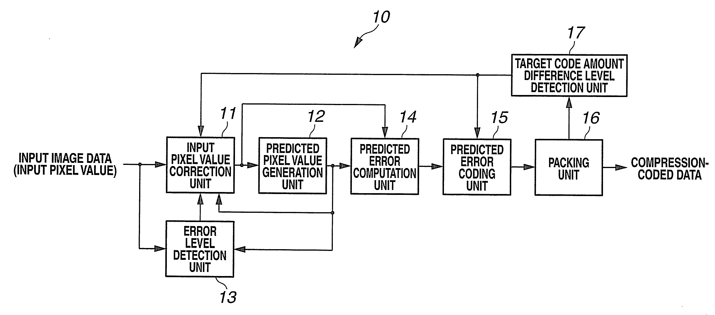
[0022]FIG. 1 is a block diagram showing an image compressor according to a first embodiment of the present invention.

[0023]The image compressor 10 shown in FIG. 1 has a predicted pixel value generation unit 12 configured to generate a predicted pixel value by referring to a past input pixel, an error level detection unit 13 configured to detect the magnitude of the difference between the predicted pixel value and an input pixel value, a target code amount difference level detection unit 17 configured to detect a target code amount difference level indicating the magnitude of an excess by which a generated code amount for the number of encoded pixels exceeds a target code amount corresponding to the number of pixels, an input pixel value correction unit 11 configured to correct less significant bit data in the input pixel value according to an error level output from the error level detection unit 13 and a target code amount difference level output from the target code amount differe...

second embodiment

[0055]FIG. 6 is a block diagram showing an image expander according to a second embodiment of the present invention.

[0056]The image expander 20 shown in FIG. 6 has an encoded data taking-in unit 21 configured to take in encoded data from the image compressor according to the first embodiment, a target code amount difference level detection unit 25 configured to detect a target code amount difference level indicating the magnitude of an excess by which a code amount consumed for a certain number of decoded pixels exceeds a target code amount corresponding to the number of pixels, a predicted error decoding unit 22 configured to decode, from variable length code data output from the encoded data taking-in unit 21, group information indicating a group to which the magnitude of a predicted error belongs and added bit data indicating a particular predicted error value in the group, thereby reproduce the predicted error, and detect a code length, a predicted pixel value generation unit 24...

third embodiment

[0071]FIG. 10 is a block diagram showing an image processing apparatus according to a third embodiment of the present invention.

[0072]The image processing apparatus 30 shown in FIG. 10 has an image compression processing unit 32 including the image compressor shown in FIGS. 1 and 2 or 5, an image expansion processing unit 34 including the image expander shown in FIGS. 6 and 7 or 9, an external memory 33, and an image processing unit 31. The image processing unit 31 temporarily stores, results of intermediate processing on input image data in the external memory 33 via the image compression processing unit 32, and reads out a plurality of intermediate processing results stored in the external memory 33 via the image expansion processing unit 34 to output final results of image processing.

[0073]According to the third embodiment, a case where irreversible compression occurs is limited to a case where the magnitude of a predicted error is equal to or larger than a predetermined value, t...


PUM


Abstract

An image compressor has an input pixel value correction unit, a predicted pixel value generation unit, an error level detection unit, a predicted error computation unit, a predicted error coding unit, a packing unit and a target code amount difference level detection unit. The predicted error coding unit encodes, by variable-length coding, group information indicating a group to which the magnitude of a predicted error belongs and added bit data indicating a particular predicted error value in the group, and performs encoding by removing less significant bit data according to a target code amount difference level in the added bit data for the predicted error if the magnitude of the predicted error is equal to or larger than a predetermined value.

Description

CROSS REFERENCE TO RELATED APPLICATION[0001]This application is based upon and claims the benefit of priority from the prior Japanese Patent Application No. 2007-180181 filed on Jul. 9, 2007; the entire contents of which are incorporated herein by reference.BACKGROUND OF THE INVENTION[0002]1. Field of the Invention[0003]The present invention relates to an image compressor, an image expander and an image processing apparatus and, more particularly, to an image compressor, an image expander and an image processing apparatus capable of controlling the amount of code by mixing reversible compression and irreversible compression on a pixel-by-pixel basis without requiring transmission of reversibility / irreversibility information (e.g. quantization scales).[0004]2. Description of the Related Art[0005]Conventionally, differential pulse code modulation (DPCM) in which the difference between an input value and a predicted value (referred to as a predicted difference) is encoded is used as a ...

Claims


Application Information

Patent Timeline
IPC IPC(8): G06K9/36H03M7/36H04N1/41H04N19/115H04N19/12H04N19/134H04N19/137H04N19/182H04N19/189H04N19/196H04N19/50H04N19/593H04N19/90H04N19/91
CPCH04N19/13H04N19/182H04N19/146H04N19/593
Inventor UETANI, YOSHIHARUKIKUCHI, YUSUKE
Owner KK TOSHIBA
Why Eureka
Try Eureka