In-line push-in wire connector

Active Publication Date: 2009-01-15
IDEAL IND INC
View PDF26 Cites 13 Cited by
  • Summary
  • Abstract
  • Description
  • Claims
  • Application Information

AI Technical Summary

Benefits of technology

[0012]The wires entering the connector through opposing ports overlap to permit the shortest possible enclosure. The terminal design permits optimum use of metal materials, thereby minimizing the cost of the connector. The husbar is disposed at an ang

Problems solved by technology

Thus, the busbar somewhat interferes with the path of the wire to create a bump/angled surface

Method used


Image

  • In-line push-in wire connector
  • In-line push-in wire connector
  • In-line push-in wire connector

Examples


Example

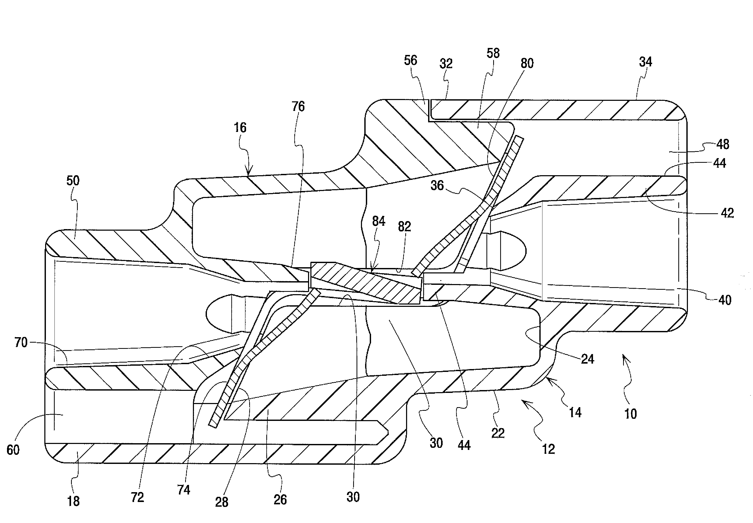
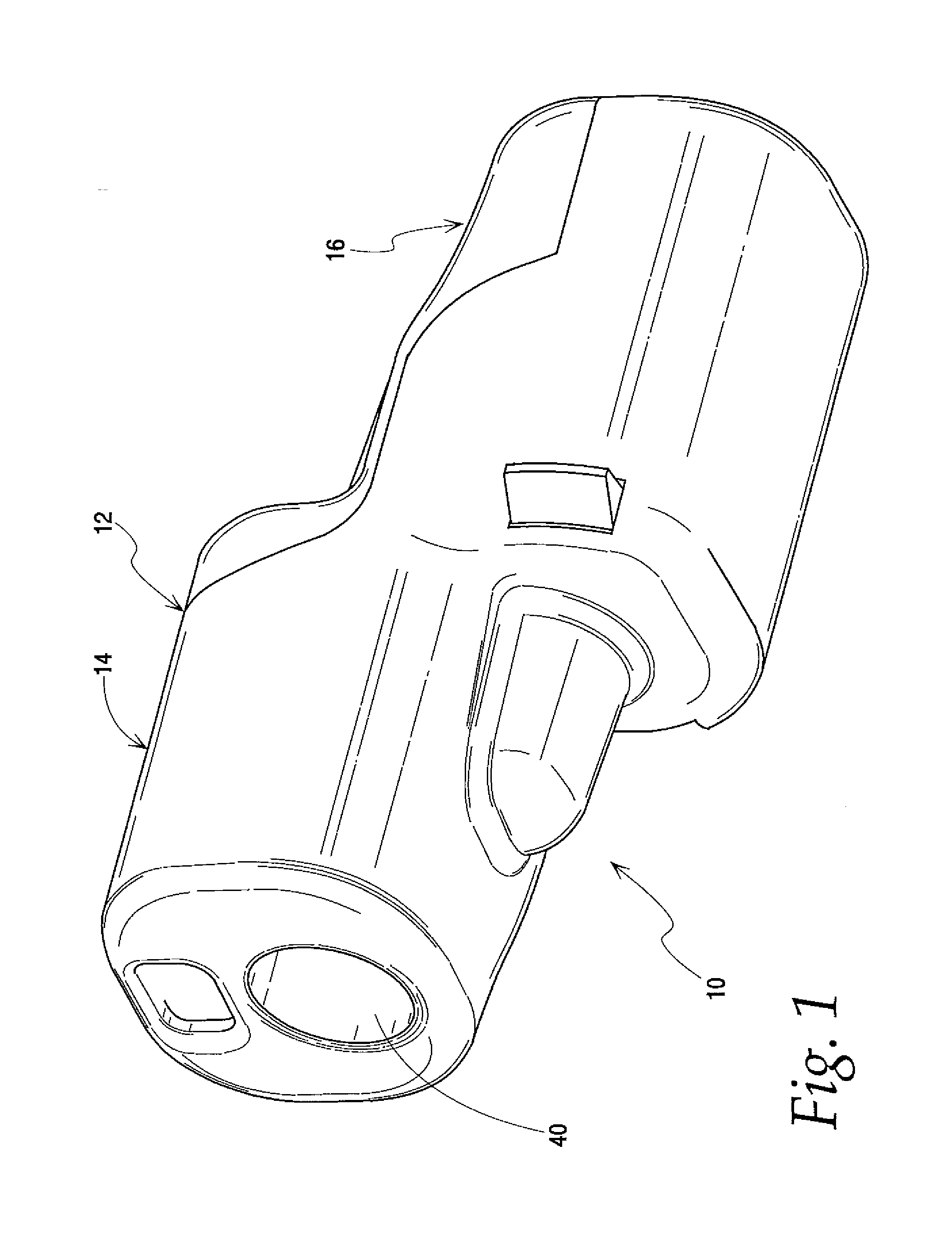
[0049]FIG. 1 illustrates the push-in connector 10 of the present invention, The push-in connector has an enclosure shown generally at 12. In this embodiment the enclosure is formed in two pieces and includes a right housing 14 and a left housing 16. Each housing has a wire entry port facing one direction and a wire receptacle box facing the other direction. A test probe opening is formed next to the wire entry port.

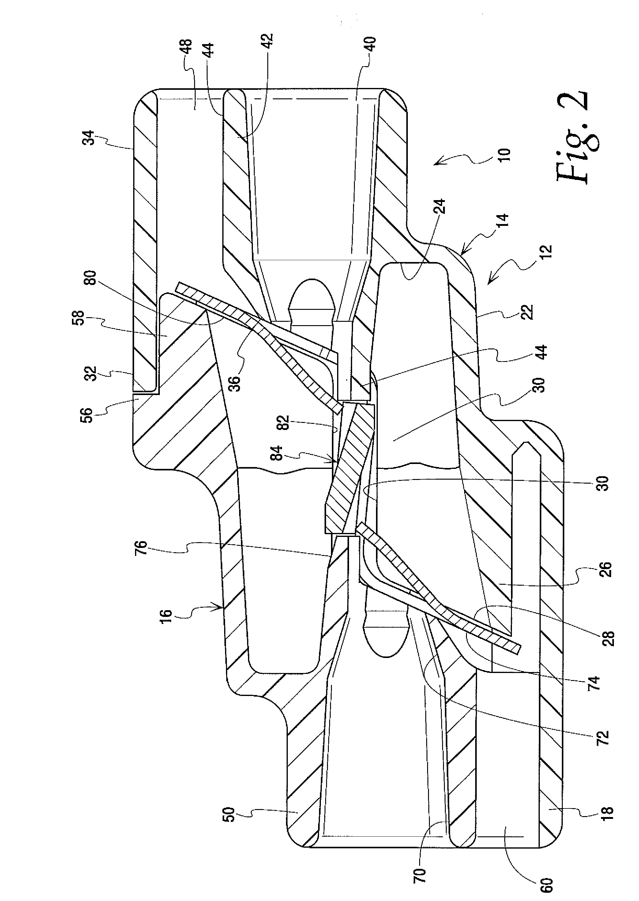
[0050]Details of the right housing 14 are seen in FIGS. 2-10. As seen in FIG. 3, the housing generally has a lower section at the left which merges with a central section that in turn joins an upper section on the right. The lower section is formed by a generally U-shaped wall 18. Wall 18 is bounded at the central section by locking apertures 20A, 20B. The central section includes a wire receptacle box 22 which has an end wall 24 and a U-shaped guide wall 26. These walls define a hollow chamber which receives the end of a wire inserted into the connector. The guide wall 2...


PUM


Abstract

A push-in wire connector has enclosure made of left and right housings. Each housing has a wire entry port and a wire receptacle box aligned with the port of the other housing. The wire entry ports face in opposite directions. A terminal is mounted in the housing and includes a busbar which is tangentially mounted to both wire ports. A spring member has spring fingers for biasing inserted conductors into engagement with opposite sides of the busbar.

Description

CROSS-REFERENCE TO RELATED APPLICATION[0001]This application claims the benefit of U.S. Provisional Application No. 60 / 948,585, filed Jul. 9, 2007, the disclosure of which is hereby incorporated herein by reference.BACKGROUND OF THE INVENTION[0002]This invention relates to push-in wire connectors. Push-in connectors operate, as the name implies, by simply pushing a stripped end of two or more wires or conductors into the connector. Once the wires are pushed into the connector no closing, crimping, twisting, insulation displacement or other manipulation of the connector is required to finish the connection, making the push-in connector advantageous from the standpoint of time needed to install it. The push-in connector must perform several tasks including electrically isolating its conductors from the surrounding environment, retaining the conductors in the connector, and providing good electrical conductivity between the conductors.[0003]The electrical isolation function is typicall...

Claims


Application Information

Patent Timeline
IPC IPC(8): H01R11/09
CPCH01R4/22H01R11/09H01R4/4827H01R4/48275
Inventor BREEN IV, DENNIS M.
Owner IDEAL IND INC
Why Eureka
Try Eureka