Electrically driven parallel shaft transmission that maintains delivered power while shifting

a parallel shaft transmission and electric motor technology, applied in the direction of electric devices, jet propulsion mountings, gearing, etc., can solve the problems of unfavorable steering and maneuverability

Inactive Publication Date: 2009-01-22
HAMILTON SUNDSTRAND CORP
View PDF23 Cites 35 Cited by
  • Summary
  • Abstract
  • Description
  • Claims
  • Application Information

AI Technical Summary

Benefits of technology

[0005]The disclosed example electric driveline assembly includes first and second electric motors that drive parallel input shafts that in turn drive the output shaft. The first and second electric motors drive a corresponding set of first and second gears that both drive the output shaft during normal operation. During gear shift changes, one of the two electric motors increases power level to maintain the desired torque output. The other motor i...

Problems solved by technology

However, in vehicles where speed and output torque is utilized for steering,...

Method used


Image

  • Electrically driven parallel shaft transmission that maintains delivered power while shifting
  • Electrically driven parallel shaft transmission that maintains delivered power while shifting
  • Electrically driven parallel shaft transmission that maintains delivered power while shifting

Examples


Embodiment Construction

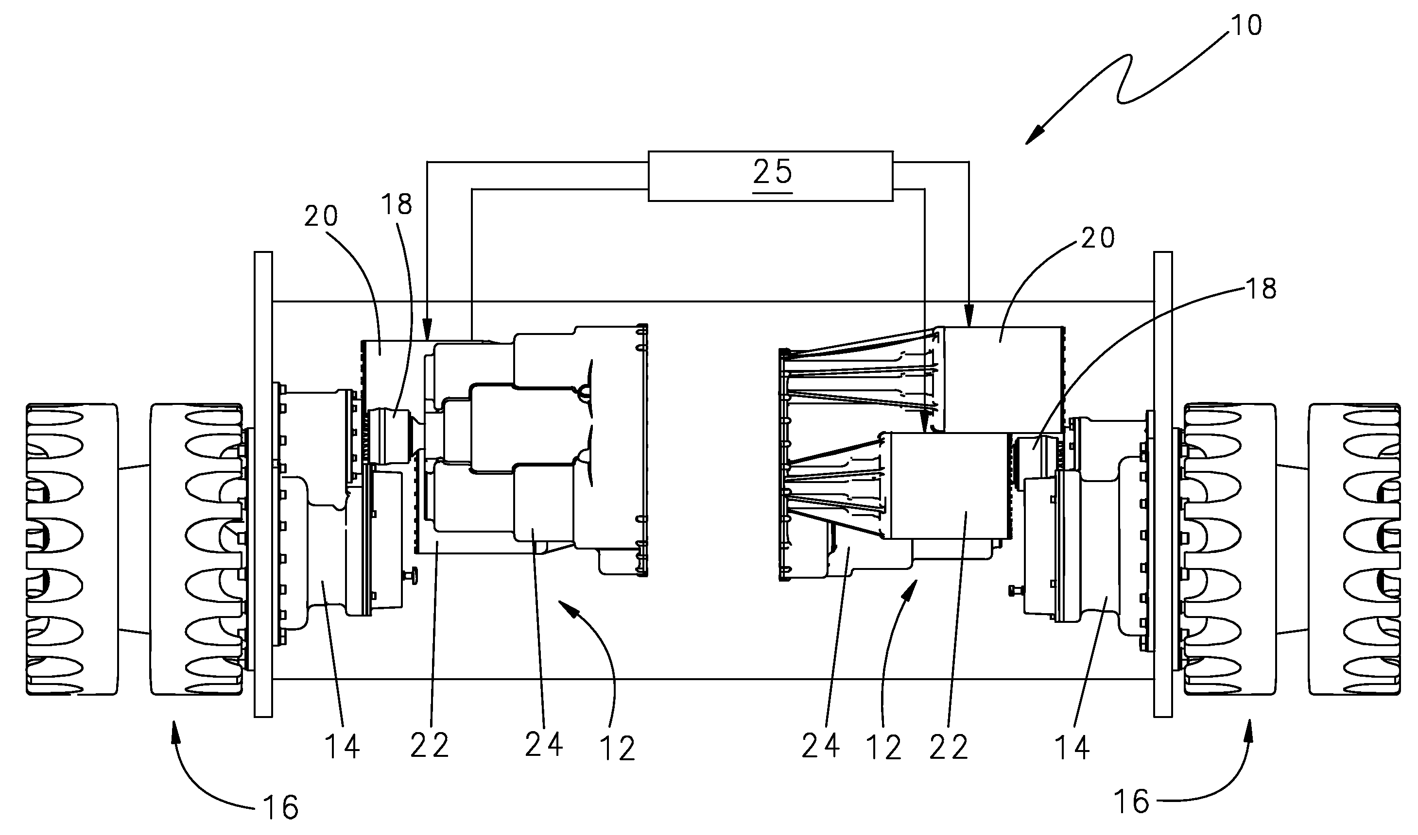
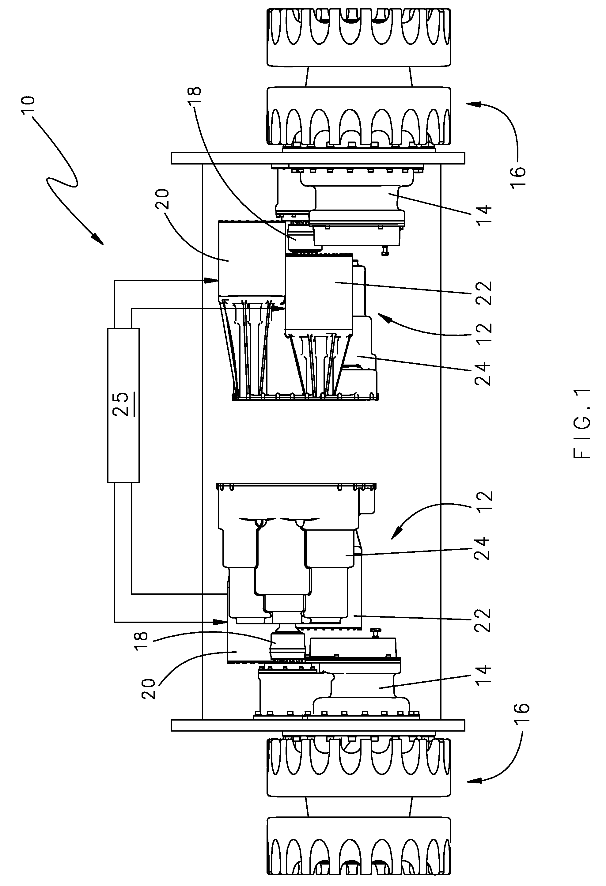
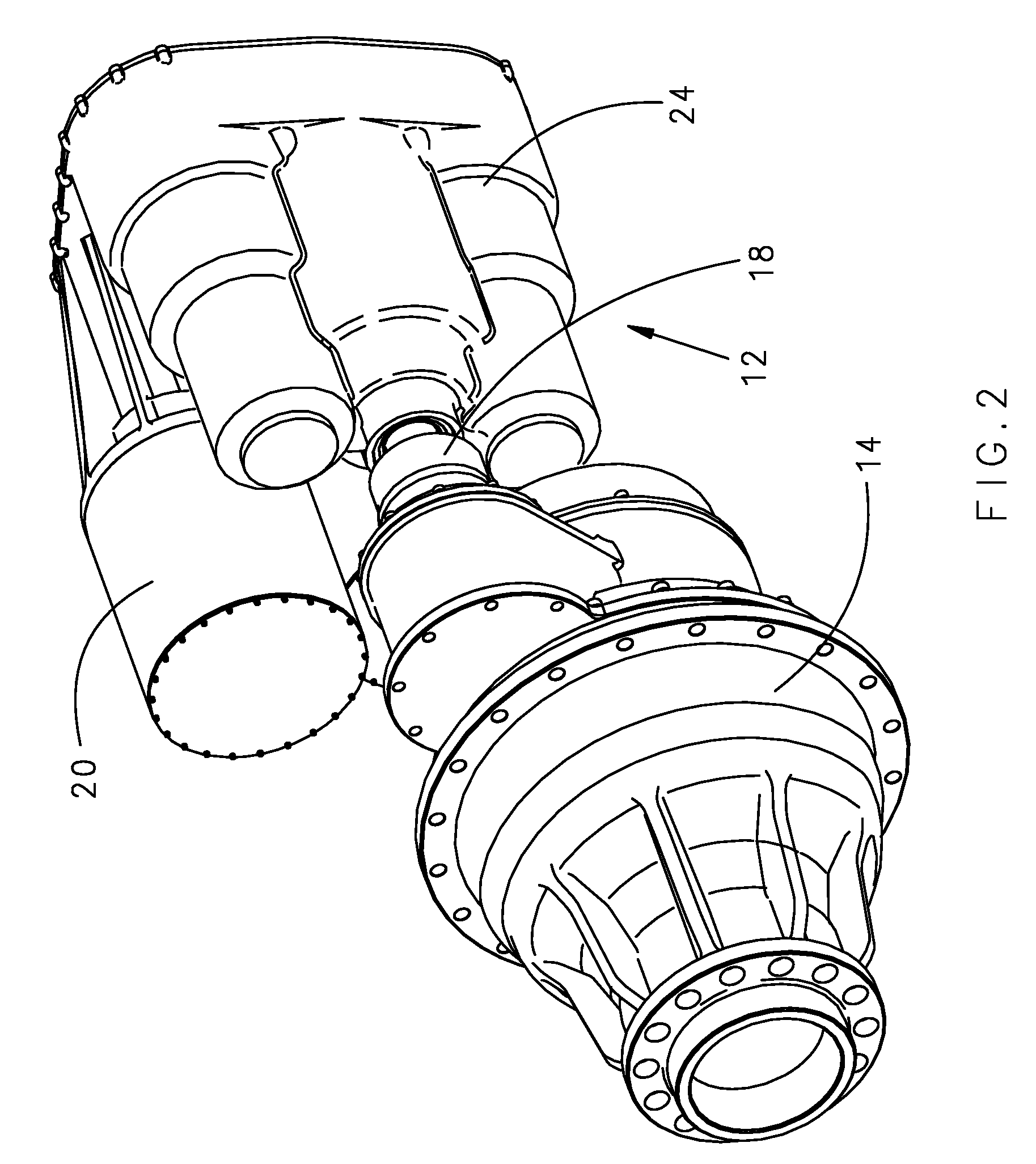
[0018]Referring to FIG. 1, an example propulsion assembly 10 comprises electrically powered driveline assemblies 12 that each include a first electric motor 20 and a second electric motor 22 that drives an output 18. The output 18 drives a final drive assembly 14 that in turn is attached and drives a sprocket assembly 16. The driveline assembly 12 is enclosed within a housing 24. A controller 25 is provided to control power output and operation of the first and second electrical motors 20, 22. The example driveline assembly 12 is utilized in heavy vehicles such as those utilizing tracks as the mode of propulsion and steering.

[0019]The driveline assemblies 12 are not mechanically linked to a power conversion device. The power conversion device may be an internal combustion engine or any other power conversion device that provides and generates electrical energy that drives the first and second electric motors 20, 22.

[0020]The example propulsion assembly 10 is utilized for a track veh...


PUM


Abstract

An electrically powered driveline assembly includes a first electric motor and a second electric motor that drive corresponding input shafts to drive an output shaft. The first and second electric motors are selectively coupled to facilitate constant torque and speed output of the output shaft during shifting and also in the event of failure of one of the electric motors.

Description

BACKGROUND OF THE INVENTION[0001]This invention generally relates to an electric motor powered driveline. More particularly, this invention relates to an electric motor powered driveline and method of operation that provides continuous torque during shifting operations.[0002]Conventional transmissions require a release of torque to facilitate a shift between desired gear ratios. In most applications such a momentary release of torque is not a concern. However, in vehicles where speed and output torque is utilized for steering, a momentary release in torque can undesirably effect steering and maneuverability.[0003]Accordingly, it is desirable to design and develop an electric motored powered driveline that switches between desired gear ratios while maintaining a constant torque output.SUMMARY OF THE INVENTION[0004]An example electric driveline assembly utilizes two electric motors that drive an output shaft that provides continuous uninterrupted torque output during gear shifting ope...

Claims


Application Information

Patent Timeline
IPC IPC(8): F16H37/06F16H3/08
CPCB60K1/02Y10T74/19233B60K7/0007B60K17/043B60K2007/003B60K2007/0061B60L2220/46B60Y2200/41F16H37/065F16H61/688F16H2003/0818F16H2061/0425Y02T10/6217Y10T74/19126Y10T477/20Y10T74/19014Y10T74/19051B60K6/46Y02T10/62
Inventor HIMMELMANN, RICHARD A.
Owner HAMILTON SUNDSTRAND CORP
Why Eureka
Try Eureka