
Electric vehicle

a technology of electric vehicles and control apparatuses, applied in the direction of dynamo-electric converter control, multiple dynamo-motor starters, transportation and packaging, etc., can solve the problems of reduced control stability, generation of oscillation, and generation of voltage oscillation caused by the reduction of control stability, so as to reduce voltage oscillation

Inactive Publication Date: 2015-06-18
TOYOTA JIDOSHA KK
View PDF32 Cites 8 Cited by
  • Summary
  • Abstract
  • Description
  • Claims
  • Application Information

AI Technical Summary

Benefits of technology

The present invention relates to a control system for electric vehicles. The invention aims to reduce voltage oscillation in the PCU (powertrain control unit) of an electric vehicle. This is achieved by adjusting the rotational speed and torque output of the electric motor(s) driving the vehicle using inverters that supply AC voltage. The control system also includes a control unit that adjusts the rotational speed and torque output of the electric motor(s) for reducing voltage oscillation. This results in a smoother operation of the electric vehicle's power system.

Problems solved by technology

Therefore, when a detection error of the current sensor that detects the current supplied to the stator coil or a detection error of the resolver is greater than a predetermined value, the control stability may be reduced, and oscillation may be generated in the rotational speed and the torque output of the synchronous motor.
In that case, voltage oscillation caused by the reduction in the control stability is also generated in the counter-electromotive voltage of the synchronous motor.
When the voltage oscillation is generated in the circuit of the PCU, high voltage is applied to electrical elements in the circuit, such as switching elements and diodes, and there is a problem that the lifetime of the electrical elements is reduced.

Method used


Image

  • Electric vehicle
  • Electric vehicle
  • Electric vehicle

Examples


Embodiment Construction

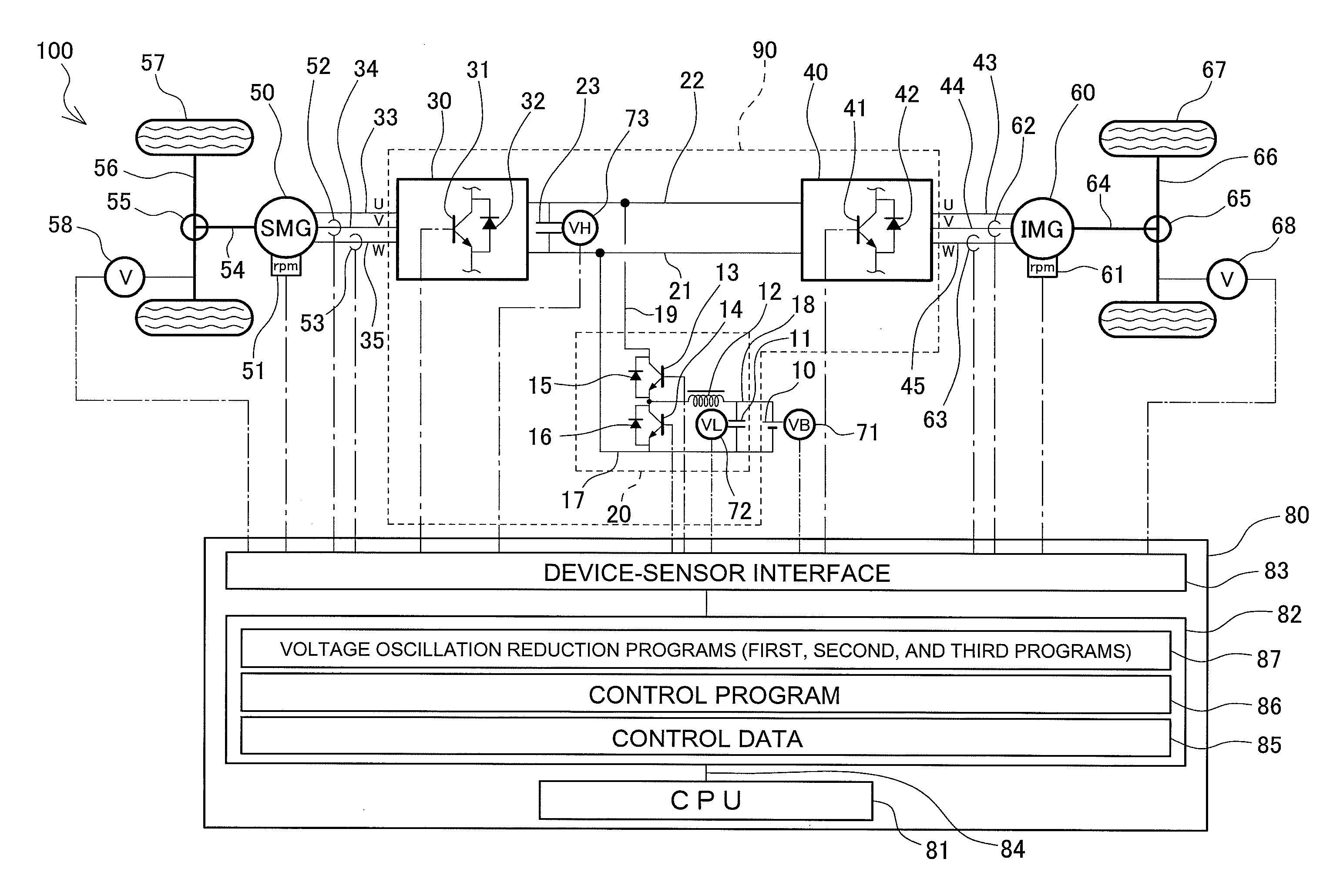
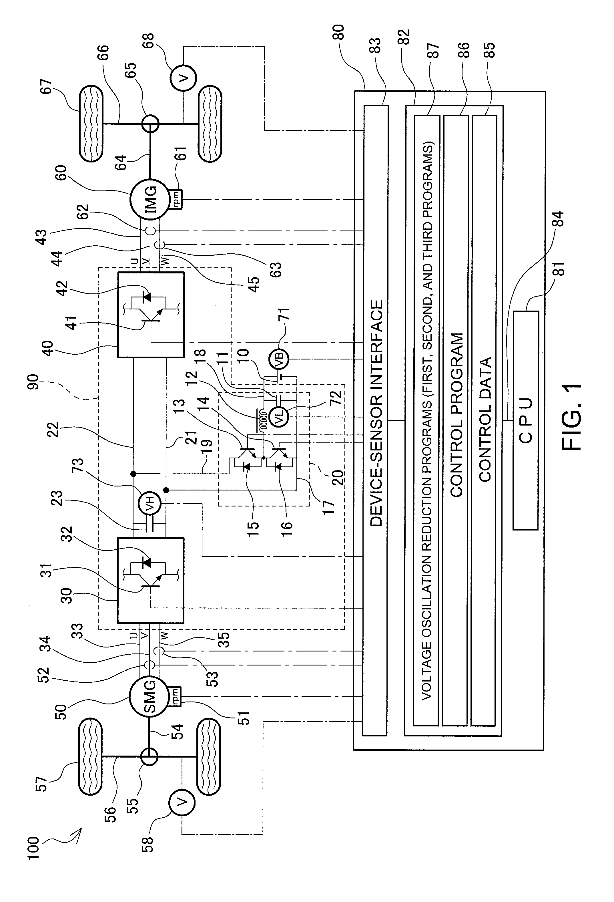
[0034]Hereinafter, embodiments of the present invention will be described with reference to the drawings. As shown in FIG. 1, an electric vehicle 100 of the present embodiment includes: a front wheel 57 driven by a synchronous motor generator 50 that is another motor for driving a vehicle; and a rear wheel 67 driven by an induction motor generator 60 that is an induction motor for driving a vehicle. The synchronous motor generator 50 may be, for example, a permanent magnet synchronous motor generator (PMSMG) including a permanent magnet incorporated into a rotor.

[0035]As shown in FIG. 1, a boost converter 20 obtains boost DC power by boosting the voltage of DC power supplied from a battery 10 that is a secondary battery that can be charged and discharged, an inverter 30 that is “another inverter” converts the boost DC power to three-phase AC power (another AC voltage), and the three-phase AC power is supplied to the synchronous motor generator 50. An inverter 40 that is an “inverter...


PUM


Abstract

An electric vehicle including: an induction motor generator; a synchronous motor generator; an inverter that converts a supplied high voltage VH to an AC voltage to be supplied to the induction motor generator and the synchronous motor generator; and a control unit that adjusts the rotational speed and torque output of the induction motor generator and the synchronous motor generator, wherein the control unit includes a voltage oscillation reduction program for causing the induction motor generator to generate voltage oscillation in a phase opposite to voltage oscillation of the high voltage VH to reduce the voltage oscillation of the high voltage VH when the high voltage VH supplied to the inverter oscillates at an amplitude equal to or greater than a predetermined voltage value due to rotation of the synchronous motor generator. As a result, the voltage oscillation in a PCU of the electric vehicle is reduced.

Description

CROSS-REFERENCE TO RELATED APPLICATION[0001]This application claims priority to Japanese Patent Application No. 2013-258200, filed on Dec. 13, 2013, which is incorporated herein by reference in its entirety.TECHNICAL FIELD[0002]The present invention generally relates to a structure of an electric vehicle, and more particularly to a configuration of a control apparatus of an electric vehicle.BACKGROUND ART[0003]A power control apparatus (PCU) including a boost converter that boosts the voltage of a battery as a power source and including an inverter that converts DC power boosted by the boost converter to AC power to supply the AC power to a motor for driving a vehicle is used in an electric vehicle, such as an electric car that drives a vehicle by a motor and a hybrid car that drives a vehicle by output of a motor and an engine. As for the motor for driving a vehicle, electric vehicles often include synchronous motors or include induction motors along with the synchronous motors. Ex...

Claims


Application Information

Patent Timeline
Patent Type & Authority Applications(United States)
IPC IPC(8): H02P5/74
CPCH02P5/74B60L9/22B60L15/025B60L2210/14Y02T10/64Y02T10/72
Inventor OTA, TAKASHI
Owner TOYOTA JIDOSHA KK
Learn More