Control device for switching power source

a technology of control device and power source, which is applied in the direction of power conversion system, dc-dc conversion, instruments, etc., can solve problems such as power consumption increas

Inactive Publication Date: 2015-09-01
FUJI ELECTRIC CO LTD
View PDF15 Cites 0 Cited by
  • Summary
  • Abstract
  • Description
  • Claims
  • Application Information

AI Technical Summary

Benefits of technology

[0021]The present invention takes this problem into account, and an object thereof is to provide a control device for a switching power source that detects an error in voltage outputted from the switching power source and reduces output voltage oscillation occurring when a control pulse signal is generated by an analog / digital conversion circuit and a DPWM circuit on the primary side of a transformer.
[0029]The present invention can detect an error in output voltage using a shunt regulator on the secondary side of a transformer of a switching power source, and reduce oscillation in output voltage, which occurs when a control pulse signal is generated by an analog / digital conversion circuit and a DPWM circuit on the primary side of the transformer, without a large increase in power consumption or area taken up by the circuit.

Problems solved by technology

However, if the number of bits of data used in a digital counter type DPWM circuit is increased by Npwm, then the control clock needs to be multiplied by 2 to the Npwm power, and thus, power consumption increases.

Method used


Image

  • Control device for switching power source
  • Control device for switching power source
  • Control device for switching power source

Examples


Embodiment Construction

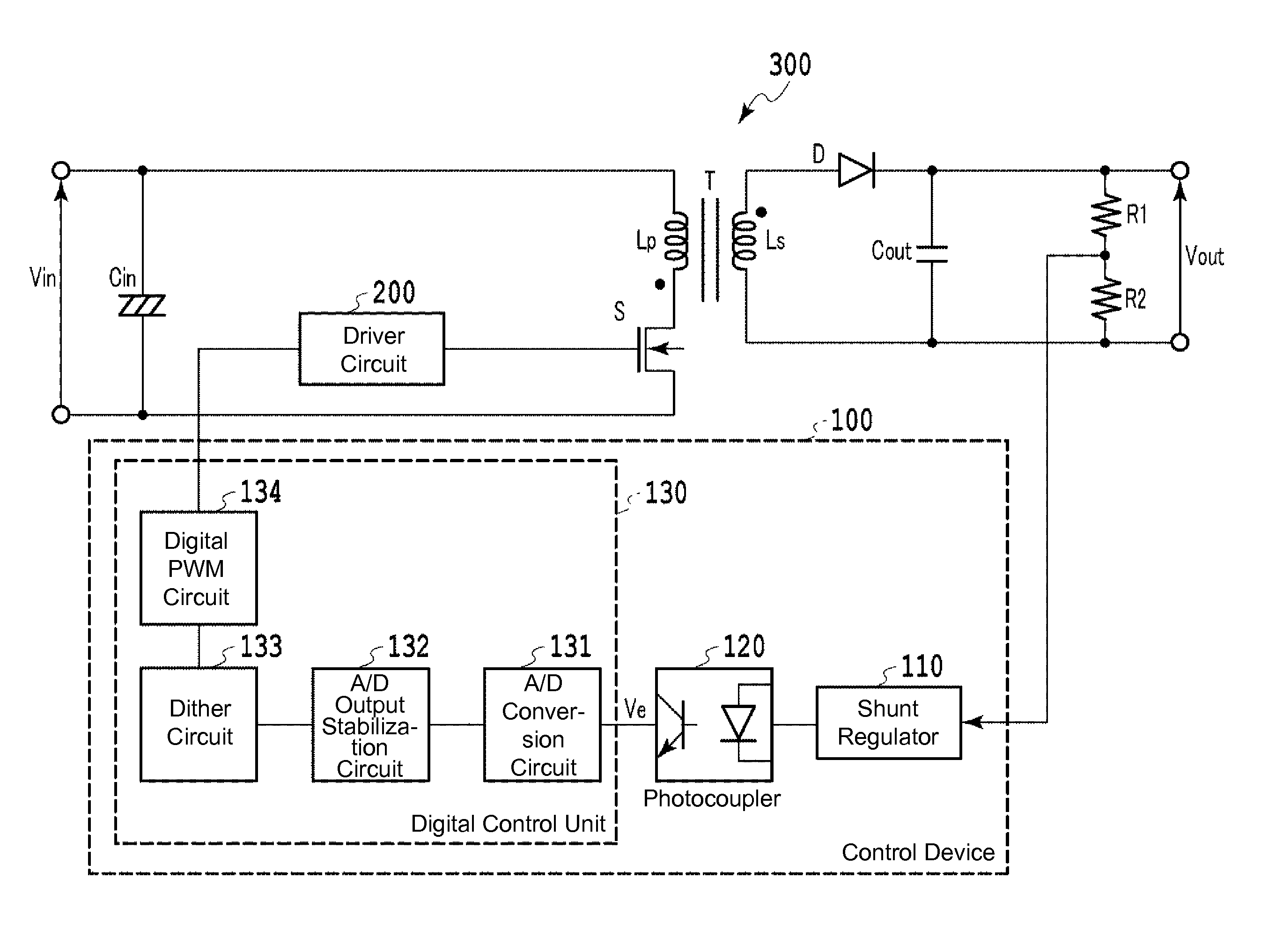
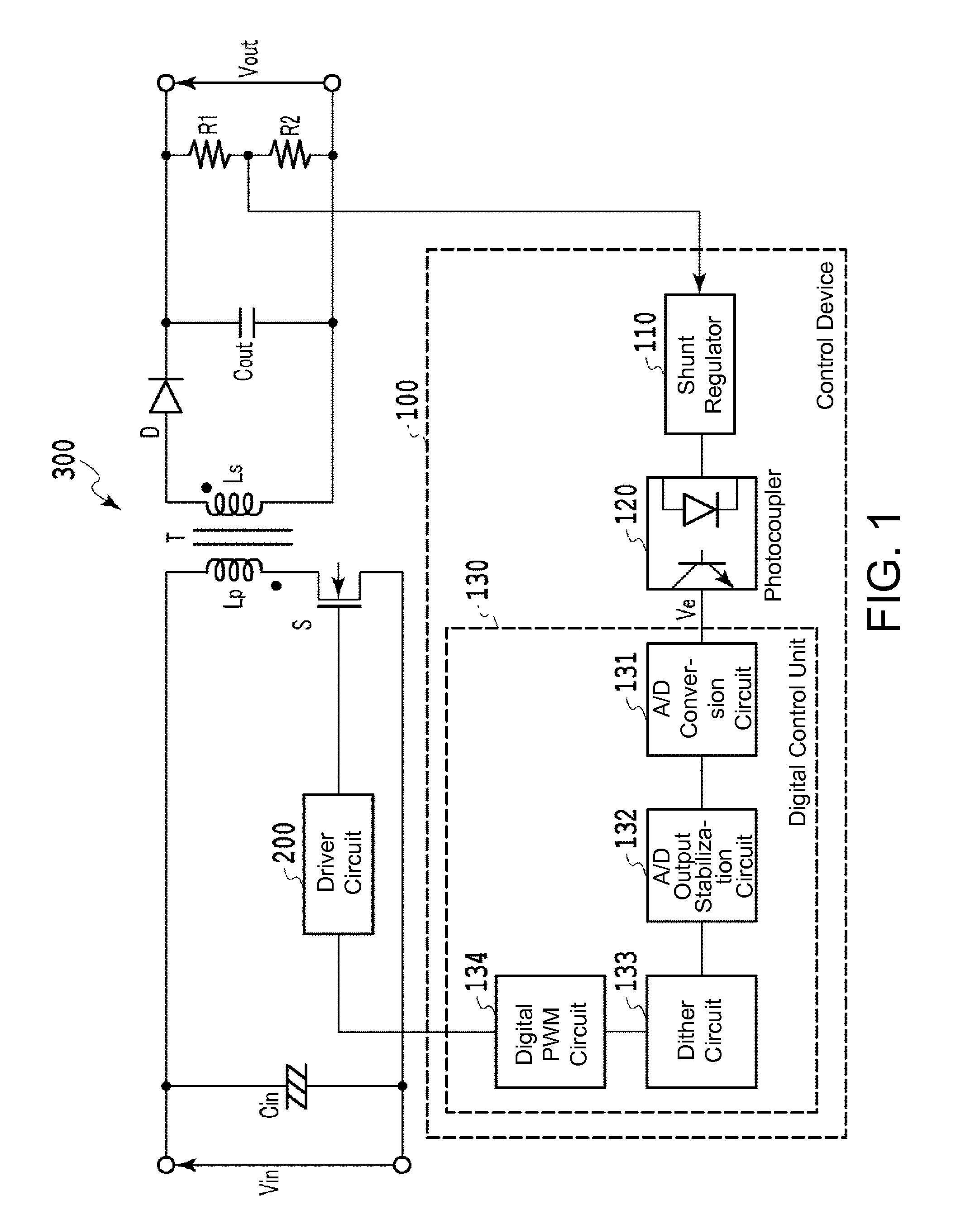
[0040]FIG. 1 shows an insulation type DC / DC converter and a control device thereof according to one embodiment of the present invention. A control device 100 of an insulation type DC / DC converter 300 includes a shunt regulator 110 that detects an error in output voltage at the secondary side of a transformer, a photocoupler 120 that transmits the detected error voltage to the primary side of the transformer, and a DPWM control unit 130 on the primary side that generates a control pulse signal having a pulse width at a duty ratio based on the error voltage.

[0041]The DPWM control unit 130 includes an A / D conversion circuit 131, an A / D output stabilization circuit 132, a dither circuit 133, and a DPWM circuit 134. The A / D output stabilization circuit 132 is provided after the A / D conversion circuit 131, and the output end of the A / D output stabilization circuit 132 is connected to the input end of the dither circuit 133.

[0042]In an embodiment of the present invention also, the dither c...


PUM


Abstract

A control device of an insulation type DC / DC converter includes a shunt regulator that detects an error in output voltage at the secondary side of a transformer, a photocoupler that transmits the detected error voltage to the primary side of the transformer, and a DPWM control unit on the primary side that generates a control pulse signal having a pulse width at a duty ratio based on the error voltage. The DPWM control unit includes an A / D conversion circuit, an A / D output stabilization circuit, a dither circuit, and a DPWM circuit. The A / D output stabilization circuit is provided after the A / D conversion circuit, and the output end of the A / D output stabilization circuit is connected to the input end of the dither circuit.

Description

BACKGROUND OF THE INVENTION[0001]1. Technical Field[0002]The present invention relates to a control device for mitigating output voltage oscillation in a switching power source that performs digital control.[0003]2. Background Art[0004]As shown in FIG. 6, conventional insulation type DC / DC converters include, in the secondary side of a transformer that outputs a prescribed voltage, a shunt regulator 710, an error amplifier, or the like that outputs an error voltage in which a difference between the output voltage and a target voltage is amplified, and additionally include an insulating element such as a photocoupler 720 or the like for sending the detected error voltage to the primary side of the transformer.[0005]The primary side of the transformer includes a pulse width modulation (PWM) circuit 730, which generates a control pulse signal having a pulse width at a duty ratio based on the error voltage, and a desired output voltage is attained by controlling a switching element by t...

Claims


Application Information

Patent Timeline
Patent Type & Authority Patents(United States)
IPC IPC(8): G05F1/00H02M3/335
CPCH02M3/33507H02M3/33523H02M1/0012
Inventor KAWASHIMA, TETSUYA
Owner FUJI ELECTRIC CO LTD
Why Eureka
Try Eureka