Converter system

Active Publication Date: 2016-01-14
ABB (SCHWEIZ) AG
View PDF10 Cites 1 Cited by
  • Summary
  • Abstract
  • Description
  • Claims
  • Application Information

AI Technical Summary

Benefits of technology

The invention reduces voltage oscillation by using carbon fibre which has higher resistivity than copper, without increasing the inductance of the DC conductors.

Problems solved by technology

A problem related to the above converter system is that in use an undesirable high frequency voltage oscillation may be generated into the DC conductors 100, 200 as a result of the operation of the converter system.
However, increasing the length of the DC conductors also increases the inductance thereof, which is not desirable.

Method used


Image

  • Converter system
  • Converter system

Examples


Embodiment Construction

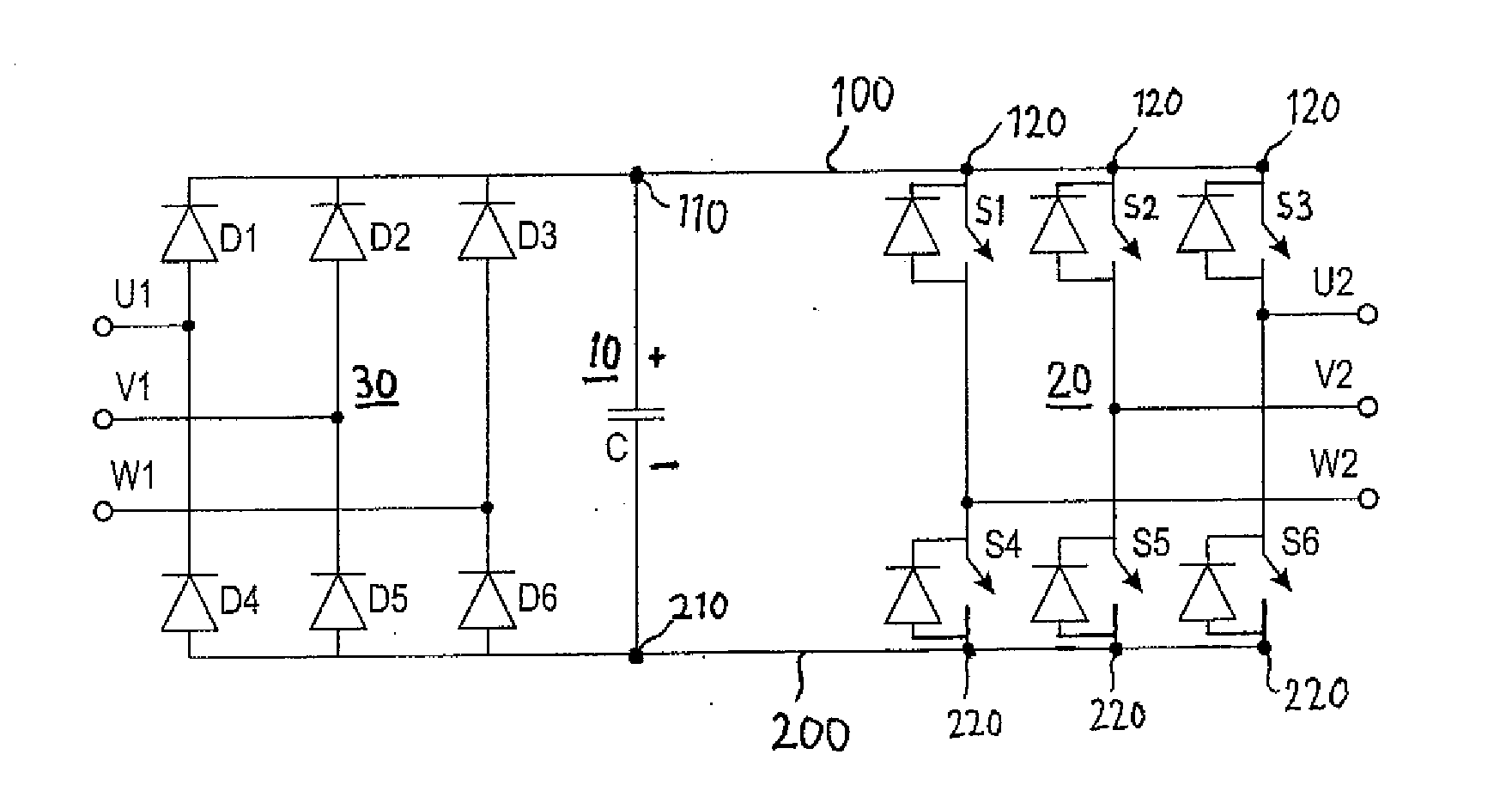
[0012]The application of the invention is not restricted to any specific system, but it may be applied to various converter systems that comprise a capacitance and an inverter. In addition, the use of the invention is not restricted to any system utilizing a specific basic frequency or to any specific voltage level.

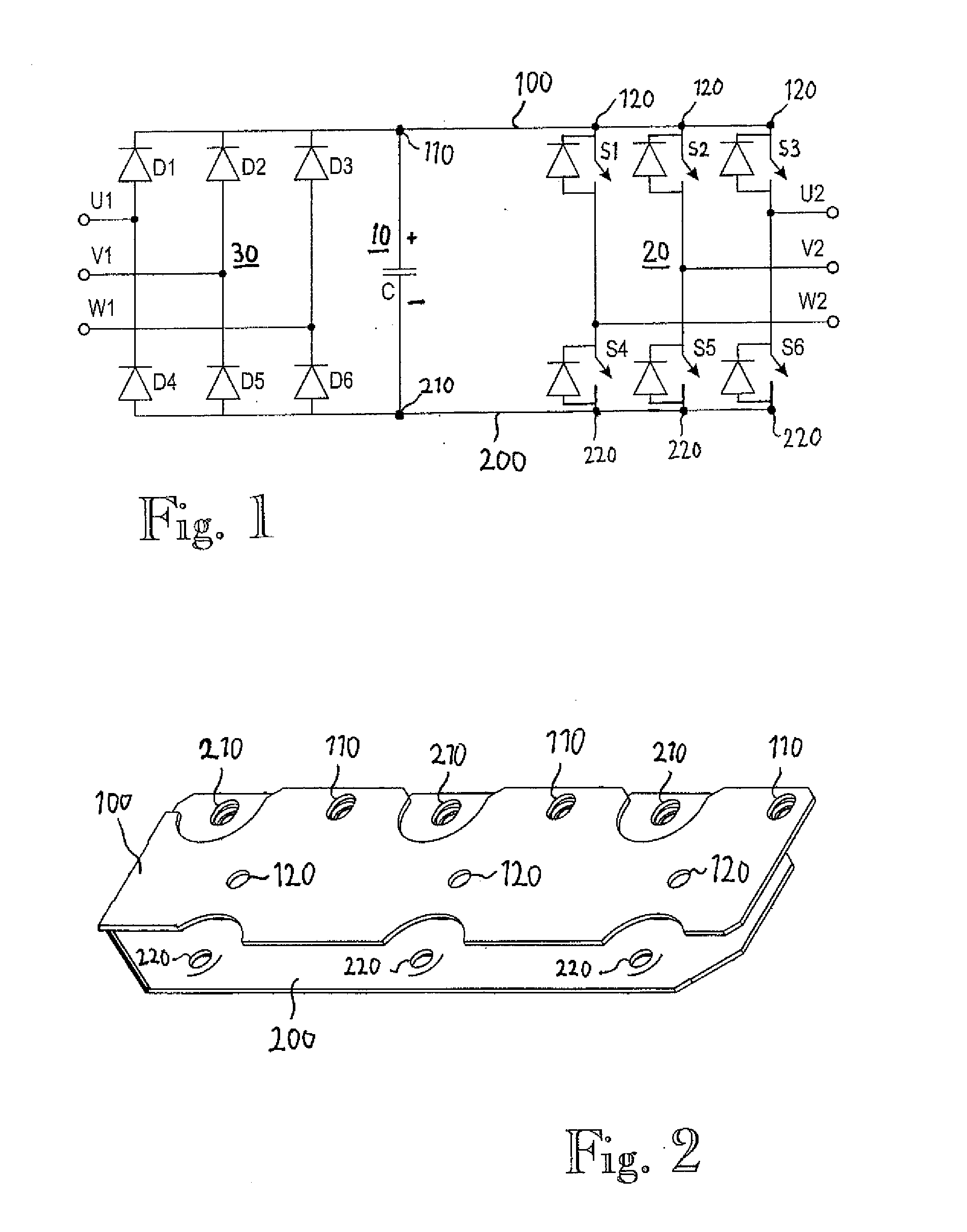
[0013]According to an embodiment, a converter system comprising a capacitance C and an inverter 20 comprising at least two controllable semiconductor switches S1 to S6 further comprises at least two DC conductors 100, 200 connected between the capacitance C and the at least two controllable semiconductor switches S1 to S6. It should be noted that the number of conductors 100, 200 between the capacitance C and the at least two controllable semiconductor switches S1 to S6 of the inverter 20 may vary and depends on the converter system in question. According to an embodiment, at least one of the at least two DC conductors 100, 200 comprises carbon fibre. According to an embo...


PUM


Abstract

A converter system comprising a capacitance (C), an inverter (20) comprising at least two controllable semiconductor switches (S1, S2, S3, S4, S5, S6), and at least two DC conductors (100, 200) connected between the capacitance (C) and the at least two controllable semiconductor switches (S1, S2, S3, S4, S5, S6), wherein at least one of the at least two DC conductors (100, 200) comprises carbon fibre.

Description

FIELD OF THE INVENTION[0001]The invention relates to a converter system.BACKGROUND OF THE INVENTION[0002]An inverter is an electrical device enabling generation of a voltage with a variable frequency. Inverters may be used in connection with motors for driving them with a variable frequency. An inverter may also be a part of a frequency converter used for driving a motor or another load, for example. A frequency converter typically consists of a rectifier and an inverter, between which there is a direct-voltage intermediate circuit. The rectifier and the inverter may also be positioned physically apart from each other, and one rectifier may feed several inverters via a common intermediate circuit or, alternatively, several rectifiers may feed one inverter. The intermediate circuit typically comprises a capacitance consisting of one or more capacitors.[0003]FIG. 1 shows an example of a converter system. The exemplary converter system may comprise a rectifier 30 and an inverter 20, be...

Claims


Application Information

Patent Timeline
IPC IPC(8): H02M7/5387H02M1/00
CPCH02M7/5387H02M7/003H01B1/04H01B5/02H02M5/458H02M7/537
Inventor MYLLYKOSKI, PIRKKAKARPPA, JAANI
Owner ABB (SCHWEIZ) AG
Why Eureka
Try Eureka