
Image forming apparatus, control method, and computer-readable storage medium therefor

Inactive Publication Date: 2008-05-01
CANON KK
View PDF1 Cites 3 Cited by
  • Summary
  • Abstract
  • Description
  • Claims
  • Application Information

AI Technical Summary

Benefits of technology

[0021] The present is directed to providing a flow which is executable according to the installation location of the image forming apparatus without greatly increasing the workload of the user registering the flow.

Problems solved by technology

However, in order to operate the many functions, the user must perform setting processing numerous times via an operation panel of the image forming apparatus, reducing ease of operation.
Thus, with traditional technology, an inappropriate flow can be executed at an installation location of the image forming apparatus.
The above problem can be solved by changing the flow registered to an image forming apparatus depending on the location of installation of the image forming apparatus, but the following problems arise in registering flows.
If the operation flow registered to the image forming apparatus is changed according to the installation location, determination as to which operation flows to register to the respective image forming apparatus becomes difficult.
As the number of image forming apparatuses, the number of operation flows, and the number of locations increase, this determination becomes increasingly difficult, and the workload for registering operation flows increases greatly.
In such a case, re-registering the operation flow according to the new installation location is necessary, and as the number of image forming apparatuses to be moved increases, the workload to re-register increases, thus greatly increasing the registering workload.

Method used


Image

  • Image forming apparatus, control method, and computer-readable storage medium therefor
  • Image forming apparatus, control method, and computer-readable storage medium therefor
  • Image forming apparatus, control method, and computer-readable storage medium therefor

Examples


first embodiment

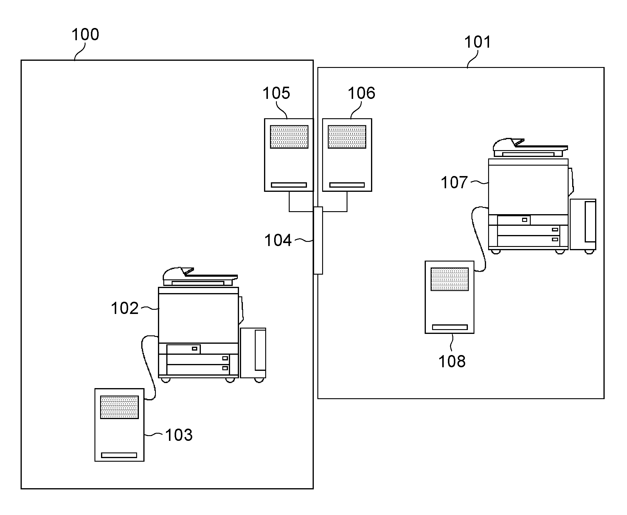
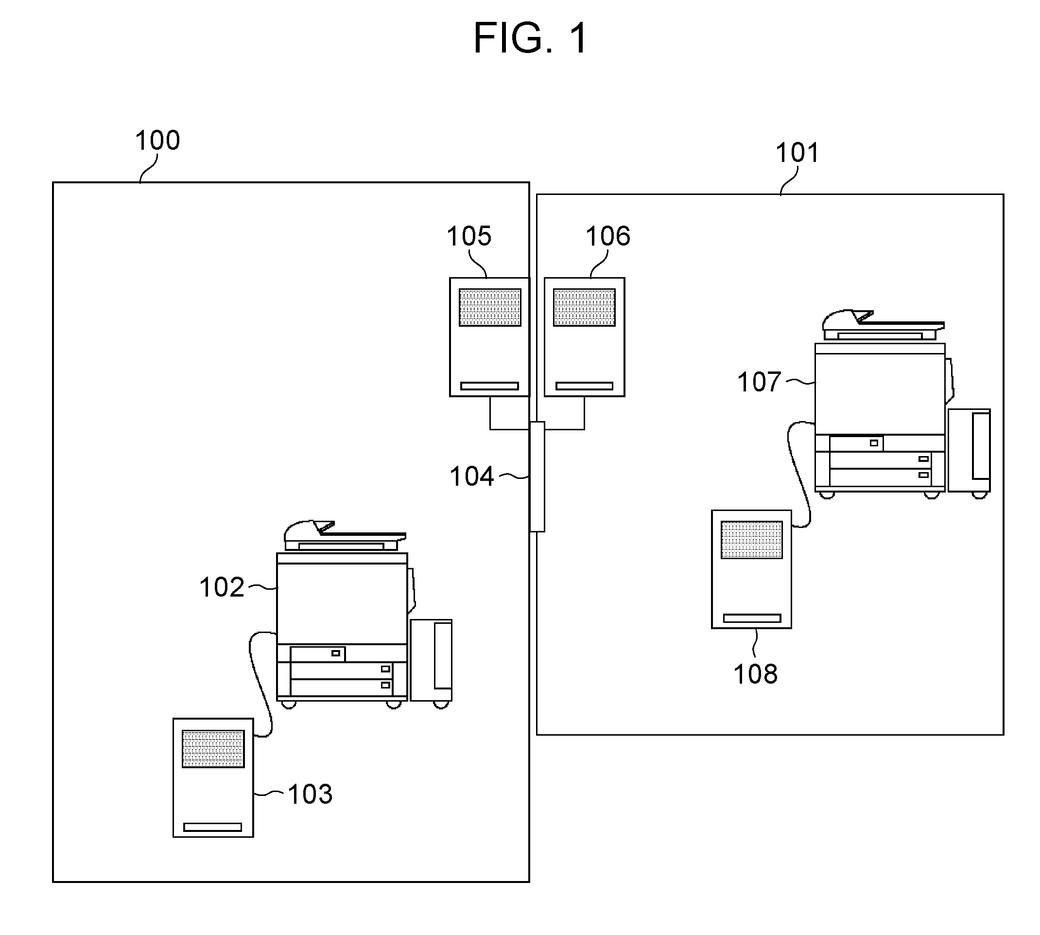
[0037]FIG. 1 is a diagram illustrating a system containing a multifunction apparatus relating to the present invention. FIG. 1 illustrates an example of an office, etc. wherein an IC card is employed to introduce a security system for managing room entry into a room.

[0038] As illustrated in FIG. 1, a reception room 100 is an environment where unauthorized persons, such as visitors may enter and leave. Conversely, a room 101 is a restricted area where only authorized persons can enter and leave.

[0039] A photocopier 102 is installed in the reception room 100. A photocopier IC card reader / writer 103 is connected to the photocopier 102, and determination can be made by reading the information recorded on an IC card as to whether the holder of the IC card can use the photocopier 102.

[0040] An electronic lock door 104 is the entrance / exit of the office room 101. The electronic lock door 104 is normally locked, preventing free entry / exit to / from the office room 101. The room entry IC car...


PUM


Abstract

A method and apparatus for obtaining room entry information associated with a user, extracting executable operation flows, and displaying an operational screen for executing the extracted operation flows.

Description

BACKGROUND OF THE INVENTION [0001] 1. Field of the Invention [0002] The present invention relates to a technique that executes workflows which are executable depending on the location where an image forming apparatus is installed. [0003] 2. Description of the Related Art [0004] In recent years, image forming apparatuses called multifunction devices have come to offer many functions. Therefore, a user is able to obtain desired output results by operating many functions. [0005] However, in order to operate the many functions, the user must perform setting processing numerous times via an operation panel of the image forming apparatus, reducing ease of operation. [0006] In order to solve the above-mentioned problem, a function has been provided which defines user operations and settings as a string of operation flows. By defining an operation flow with such a function, a button is displayed for executing processing based on the operation flow. Upon the user instructing with the button,...

Claims


Application Information

Patent Timeline
IPC IPC(8): G06F7/04
CPCG06F21/608G06F3/1285G06F2221/2111G06F2221/2117G06F2221/2153G06Q10/06H04N1/00347H04N2201/3214H04N2201/3235H04N2201/3276G06F3/1207G06F3/1222G06F3/1238G06F3/1258G06F21/84
Inventor FUJIKAWA, SHINJI
Owner CANON KK
Learn More