Transmission system, transmission device, packet loss ratio measurement method, and packet loss ratio measurement program

Inactive Publication Date: 2014-05-29
NEC CORP
View PDF2 Cites 4 Cited by
  • Summary
  • Abstract
  • Description
  • Claims
  • Application Information

AI Technical Summary

Benefits of technology

The present invention provides a way to measure packet loss ratio between devices on a transmission path without increasing the band of the OAM frame. This is done by copying the OAM frame when the data frame is an OAM frame and calculating the packet loss ratio using the copied OAM frame. This results in faster processing times and reduced processing amounts. Overall, this invention offers a more efficient way to measure packet loss ratio and is useful in transmission systems and devices.

Problems solved by technology

Loss of the data packet stops the communication on the network or causes a great deterioration in the communication speed and the communication quality, so that the packet loss ratio needs to be suppressed to a specific numerical value or less.
However, the method of the single end LM protocol depicted in Non-Patent Document 1 shown in FIG. 6 and FIG. 7 can only measure the packet loss ratio in MEG by having transmission devices at specific two points on the transmission path as MEPs and taking those MEPs as both ends.
This causes complication in the management for setting each session.
Further, each of the sessions transmits / receives the OAM frame by each MEG without synchronizing with each other, so that the measurement time in each MEG is not necessarily consistent.
In such case, it is difficult to specify the occurrence point.
When there is an inversion of the transmission order occurred as shown in FIG. 9, the counter value contained in the OAM frame becomes invalid, so that an accurate packet loss ratio cannot be calculated.
Therefore, the technique which requires actions for adding new data by processing the OAM frame in the relay device in the middle of the transmission path such as the technique depicted in Patent Document 1 has a risk of causing inversion of the transmission order as shown in FIG. 9.
That is, none of the techniques depicted in Patent Documents 1 to 4 can overcome the above-described issue.

Method used


Image

  • Transmission system, transmission device, packet loss ratio measurement method, and packet loss ratio measurement program
  • Transmission system, transmission device, packet loss ratio measurement method, and packet loss ratio measurement program
  • Transmission system, transmission device, packet loss ratio measurement method, and packet loss ratio measurement program

Examples


embodiment

Second Expansion of Embodiment

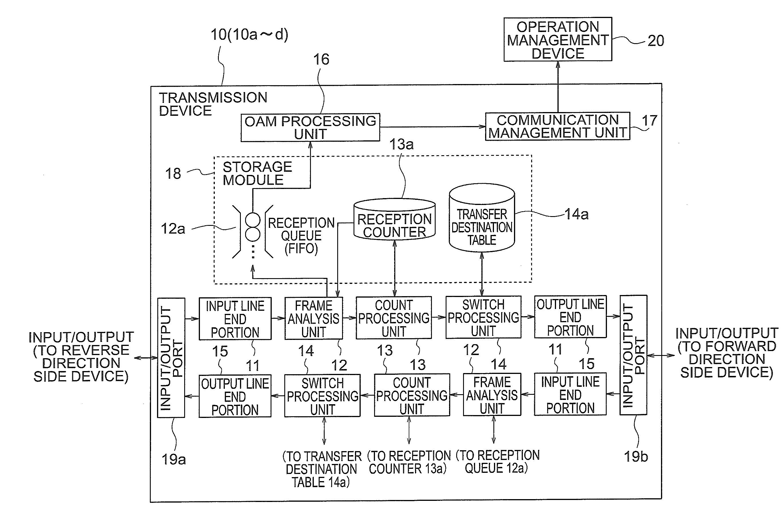
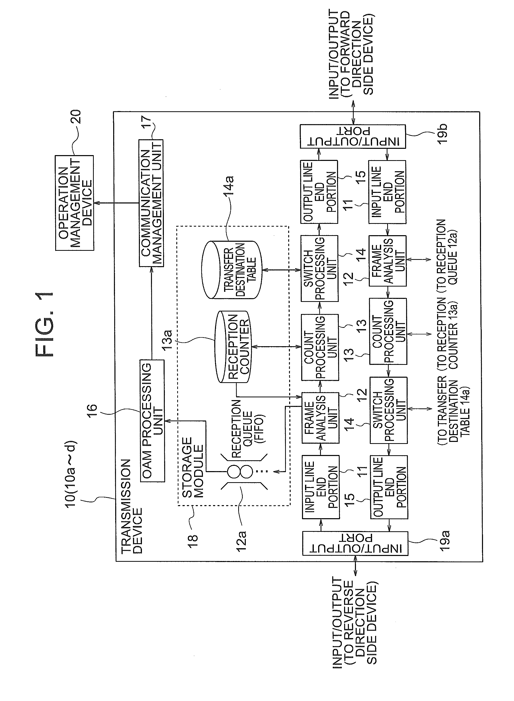
[0097]Further, while the count processing unit stores the received frame number in the storage module 18 in the embodiment described above, a time stamp value contained in the data frame may be stored instead of the received frame number and the OAM processing unit may calculate the delay time instead of the packet loss ratio. Hereinafter, this will be described in more details.

[0098]Other than the above-described LM protocol, one-way DM (Delay Measurement) protocol and two-way DM protocol as the methods for measuring the delay time in a network are defined in Non-Patent Document 1. The DM protocols are the methods similar to those of the packet loss ratio, which measure the delay time regarding transmission on the network by using time stamp values instead of the counter values.

[0099]That is, when calculating the delay time by transferring the time stamp values to the reception queue instead of the counter values in the case of a delay-measurement OAM ...


PUM


Abstract

In a transmission system capable of measuring packet loss ratio between arbitrary devices upon a transmission path without increasing bandwidth of an OAM frame band, a plurality of transmission devices which have been disposed upon a transmission path are provided with a frame analysis unit which receives data frames so as to analyze the type of the data frames, a count processing unit which stores the number of received frames included in the data frames into storage module provided beforehand, an output line end portion which outputs the data frames, and an OAM processing unit which calculates the packet loss ratio in the transmission path using the number of received frames. The frame analysis unit has a function which, if the data frames are OAM frames, copies the data frames and the OAM processing unit has a function which calculates the packet loss ratio using the copied OAM frames.

Description

TECHNICAL FIELD[0001]The present invention relates to a transmission system, a transmission device, a packet loss ratio measurement method, and a packet loss ratio measurement program. More specifically, the present invention relates to a transmission system and the like capable of making it possible to efficiently measure the packet loss ratio between arbitrary devices on a transmission path.BACKGROUND ART[0002]Ethernet (registered trademark) is a communication standard widely used in a computer network (LAN: Local Area Network) of a small scale area such as a network built within a same building. Recently, in order to reduce the network operation cost and the like, there is presented a type of network in which functions regarding network remote surveillance are added to Ethernet for expanding Ethernet to be used for WAN (Wide Area Network) which is a larger scale network. This is called Ethernet OAM (Operations, Administrations, Maintenance).[0003]The Ethernet OAM is standardized ...

Claims


Application Information

Patent Timeline
IPC IPC(8): H04L12/26H04L47/2466
CPCH04L43/0829H04L43/106H04L43/0835H04L43/0841H04L43/0852
Inventor SAKURAI, AKIRATANAKA, HIROSHIUMAYABASHI, MASAKI
Owner NEC CORP
Why Eureka
Try Eureka