Seal member

Inactive Publication Date: 2013-06-13
ROKI CO LTD
View PDF4 Cites 2 Cited by
  • Summary
  • Abstract
  • Description
  • Claims
  • Application Information

AI Technical Summary

Benefits of technology

The present invention aims to provide a seal member that can effectively seal a seal member and a head cover without adding extra parts or assembly works, and without causing shifting due to thermal deformation or wear and tear. The seal member has a flanged portion and a fixing wall portion that engage with the mount hole to prevent shifting. It also has a reinforcing member to ensure strength in both the axial and radial directions, ensuring a reliable seal.

Problems solved by technology

However, in the seal member attaching method disclosed in the Patent Document 1, since the supporting member of the seal member is fastened in a fixed manner, the number of the parts or members increases, which results in increase in weight of entire structure and increase in assembling or mounting working processes as well as difficulty of attaching and / or detaching the seal member, thus being inconvenient.
Moreover, in the seal member attaching method disclosed in the Patent Document 2, since the seal member and the head cover are assembled in protrusion-recess engaging manner, there is a possibility of causing a fear of shifting in assembled state due to thermal deformation, vibration, wearing and the like, which may result in damage on sealing performance, thus also being inconvenient.

Method used


Image

  • Seal member
  • Seal member
  • Seal member

Examples


first embodiment

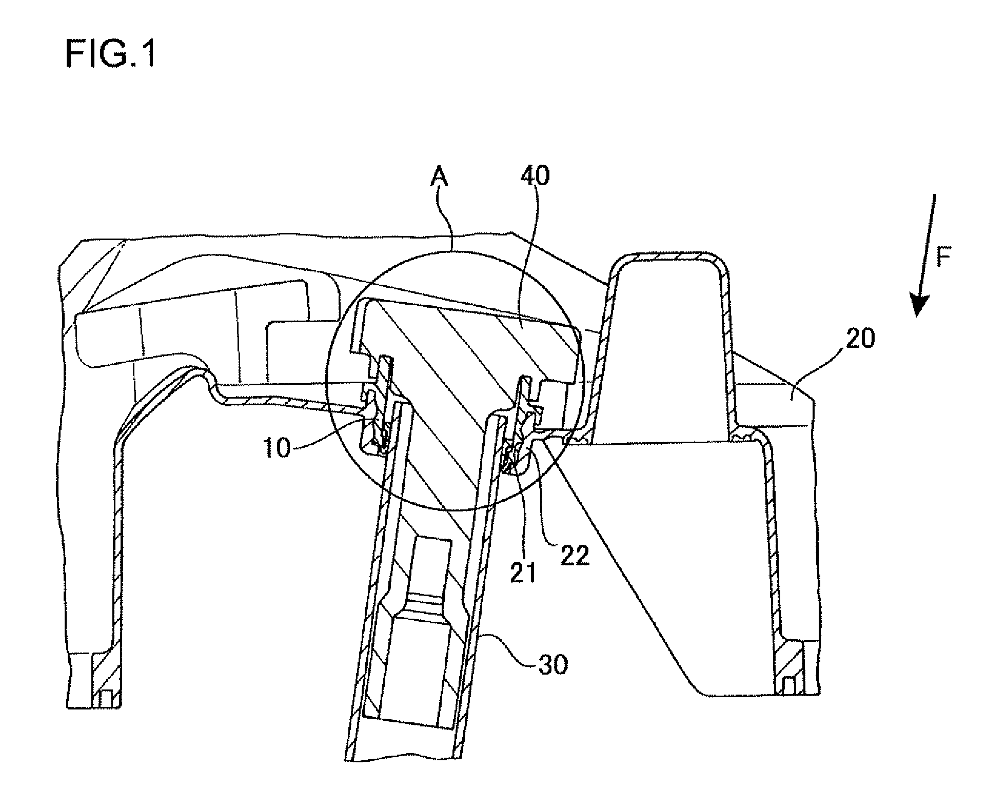
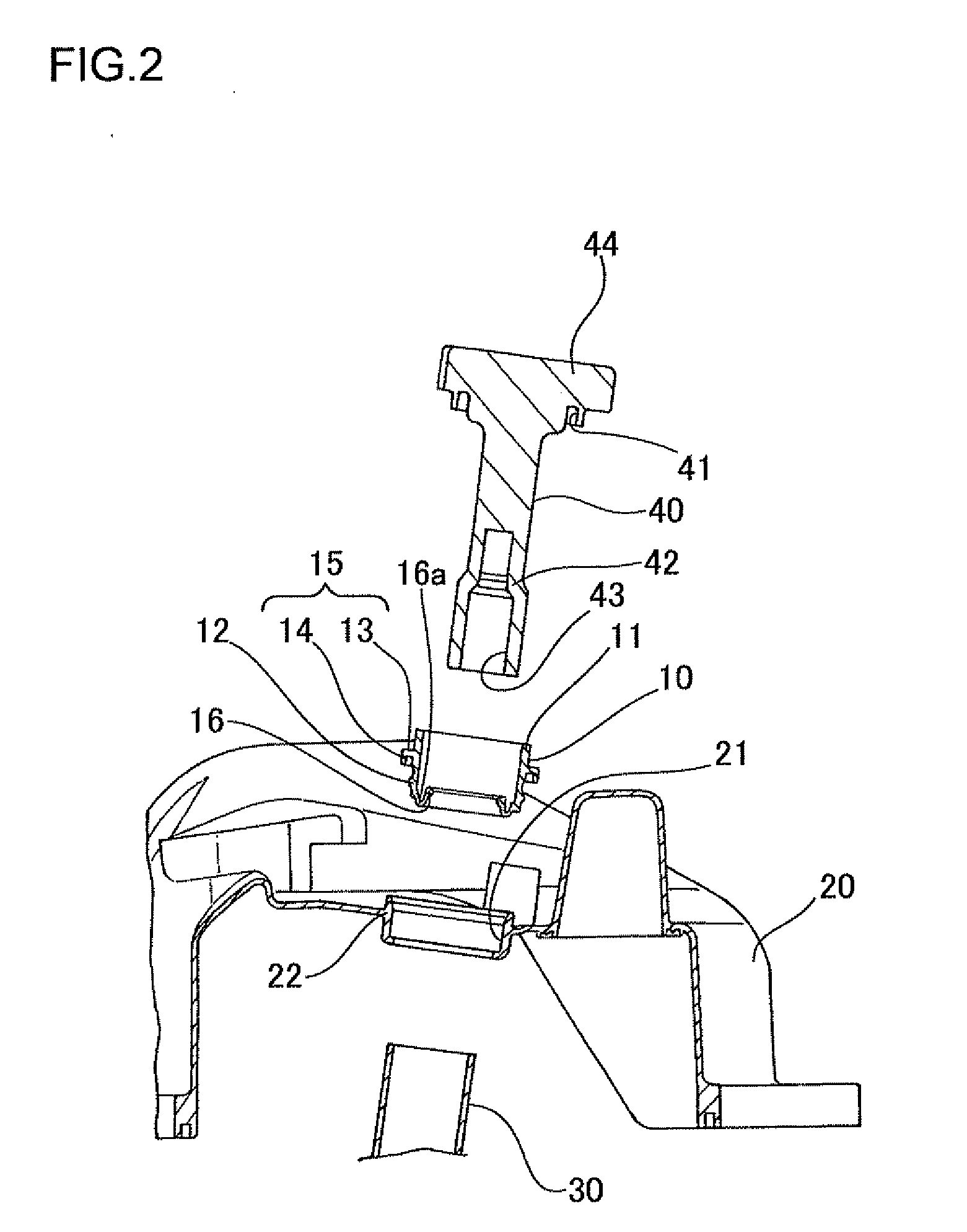
[0032]FIG. 1 is a sectional view showing a mounting state of a seal member according to a first embodiment of the present invention, FIG. 2 is a sectional view illustrating a developed state of the seal member of the first embodiment, FIG. 3 is a perspective view showing the seal member, and FIG. 4 is an enlarged view showing an encircled portion A in FIG. 1.

[0033]As shown in FIGS. 1 and 2, the seal member 10 according to the present embodiment is formed so as to provide a ring or annular shape. When the seal member 10 is inserted, along an insertion direction F, into the mount hole 21 formed in the head cover 20 of an internal combustion engine, and assembled between a peripheral wall portion 22 of the mount hole 21 and the tubular (cylindrical) member 30 fixed to the internal combustion engine.

[0034]As shown in FIG. 3, the seal member 10 has one and another ends in the axial direction thereof. The one end is formed with an axial-direction seal portion 11 in a manner projecting fro...

second embodiment

[0046]FIG. 5 is a sectional view of a seal member according to the second embodiment of the present invention. It is further to be noted that members or parts same as or similar to those of the first embodiment are described by adding the same reference numerals and detailed explanations thereof are omitted herein.

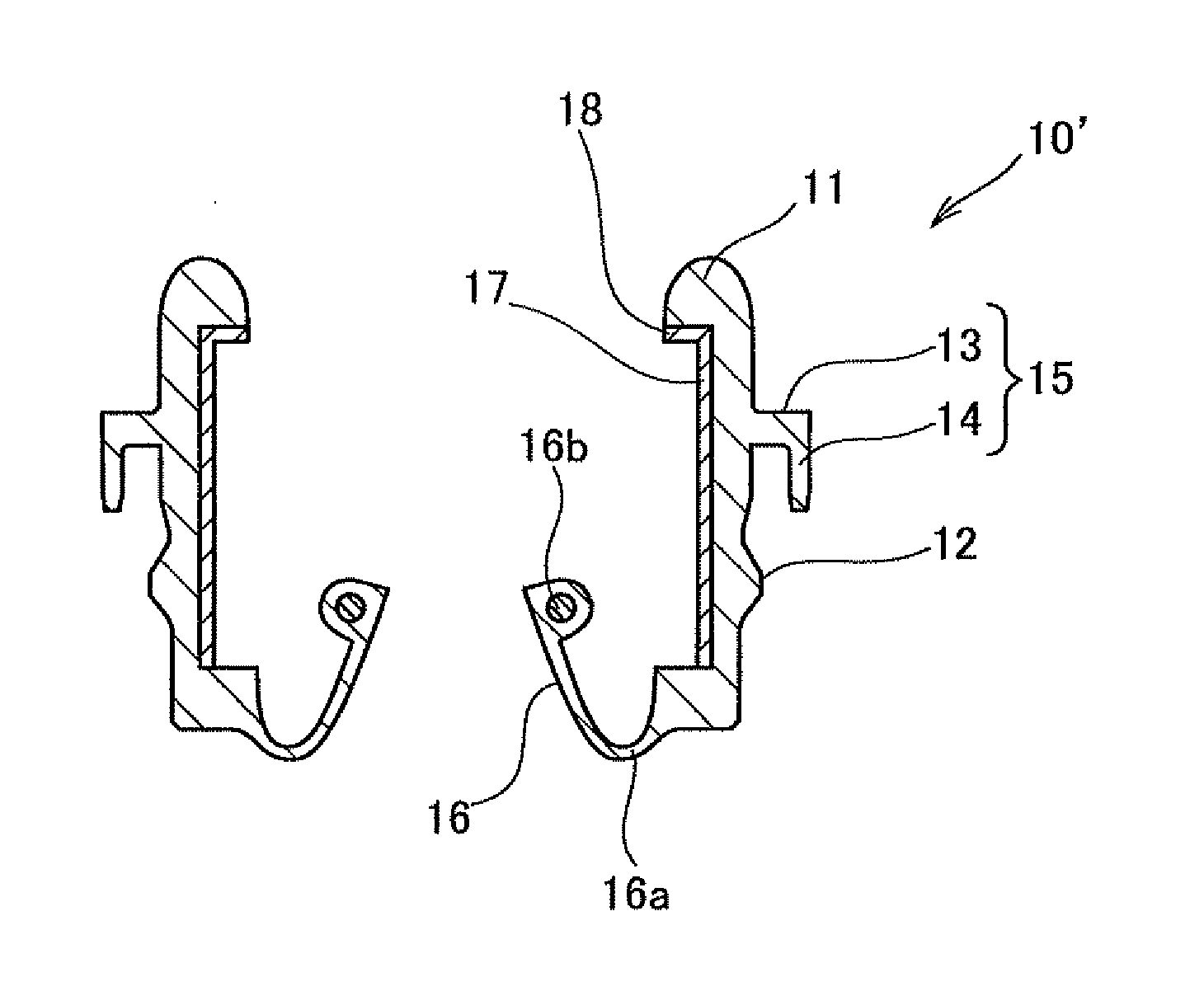
[0047]As shown in FIG. 5, the seal member 10′ according to the second embodiment is formed so as to provide a ring or annular shape, and when the seal member 10′ is inserted into the mount hole 21 formed in the head cover 20, the seal member 10′ is fitted and assembled between the peripheral wall portion 22 of the mount hole 21 and the tubular member 30 fixed to the internal combustion engine.

[0048]Further, similar to the seal member 10 according to the first embodiment mentioned hereinbefore, the seal member 10′ is provided, at axial one end thereof, with the axial-direction seal portion 11, and at another end thereof, with a diameter-direction seal portion 12. The axial-...


PUM


Abstract

A seal member has a ring shape which is assembled in a portion between a tubular member to be inserted into and fixed to a mount hole formed to a head cover of an internal combustion engine and a peripheral wall portion of the mount hole. The seal member is provided with an axial-direction seal portion formed to axial one end portion of the seal member, and a diameter-direction seal portion formed to another one end of the seal member. A fixing member configured to fix movement in a diameter direction of the seal member between the axial-direction seal portion and the diameter-direction thereof is formed along a peripheral wall portion of the mount hole.

Description

BACKGROUND OF THE INVENTION[0001]1. Field of the Invention[0002]The present invention relates to a seal member, and particularly, to a seal member interposed between an ignition plug mount hole formed to a head cover of an internal combustion engine and a mount member into which an ignition plug is inserted.[0003]2. Related Art[0004]It is conventionally known that a head cover made of synthetic resin is attached to an upper portion of an internal combustion engine for the purpose of realizing lightweight and improving design performance. In such structure, an ignition plug is mounted to the upper portion of the internal combustion engine, the ignition plug is inserted into a mount member such as tubular (cylindrical) plug tube, and the plug tube is inserted into an ignition plug mount hole formed to the head cover.[0005]In the above conventional structure, a seal member is also interposed between the plug tube and the ignition plug mount hole for the purpose of liquid-tightly sealin...

Claims


Application Information

Patent Timeline
IPC IPC(8): F02F11/00
CPCF02F11/00F16J15/3276F16J15/3268F16J15/3212
Inventor SATO, TAISUKESUZUKI, TAKENORI
Owner ROKI CO LTD
Why Eureka
Try Eureka