Adjustable target mount

Active Publication Date: 2009-01-22
ACTION TARGET
View PDF30 Cites 2 Cited by
  • Summary
  • Abstract
  • Description
  • Claims
  • Application Information

AI Technical Summary

Benefits of technology

[0006]It is an object of the present inve

Problems solved by technology

While target mounts are available, they suffer from some limitations which make them more difficult to use.
These arms are a nuisance when not in use as they may cause ricochets or may interfere with shooting at the targets which are in use and which are positioned adjacent one of these arms.
If a front row is not in use, the target mounts may partially obst

Method used


Image

  • Adjustable target mount
  • Adjustable target mount
  • Adjustable target mount

Examples


Example

[0025]It will be appreciated that the drawings are illustrative and not limiting of the scope of the invention which is defined by the appended claims. The various embodiments shown accomplish various aspects and objects of the invention.

DETAILED DESCRIPTION

[0026]The drawings will now be discussed in reference to the numerals provided therein so as to enable one skilled in the art to practice the present invention. The drawings and descriptions are exemplary of various aspects of the invention and are not intended to narrow the scope of the appended claims.

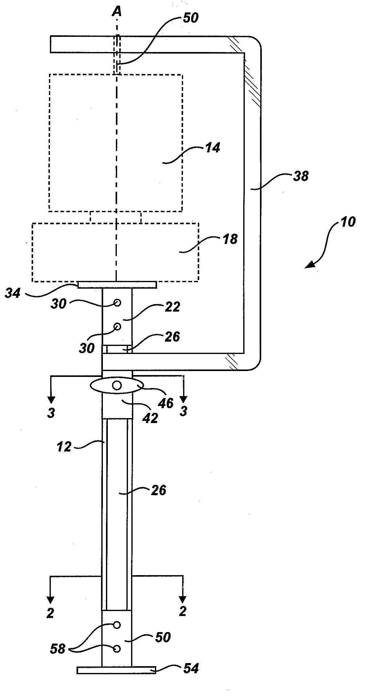
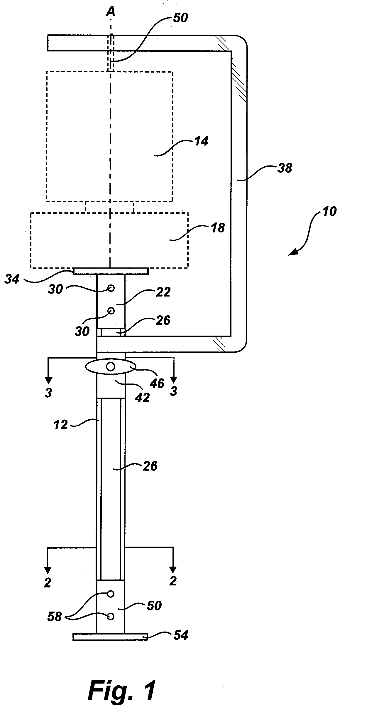
[0027]Turning to FIG. 1, a front view of a target mount according to the present invention is shown. The target mount, indicated generally at 10, includes a base 12 configured to support a target 14 in a desired configuration. A target actuator 18 may be used, if desired, between the target 14 and base 12 so that the target 14 may be moved, such as by rotating the target 14, as may be desired. (Unless specifically noted, referenc...


PUM


Abstract

An adjustable target mount allows the height of the mount to be adjusted. Additionally, the mount is adjustable to accommodate a variety of different targets and target actuators, and may be quickly moved out of the line of fire without requiring disassembly or removal of the target mount.

Description

RELATED APPLICATIONS[0001]The present application claims the benefit of prior U.S. application Ser. No. 60 / 715,360, filed Sep. 8, 2005.FIELD OF THE INVENTION[0002]The present invention relates to an adjustable target mount. More specifically, the present invention relates to a target mount for use in a shooting range or similar facility.STATE OF THE ART[0003]Target mounts are commonly used in shooting ranges and similar facilities to hold or position bullet targets. While target mounts are available, they suffer from some limitations which make them more difficult to use. In mounting targets, it is sometimes necessary to utilize a target mount which not only attaches to the bottom of a target, but which supports the top of the target as well. Such mounts have arms which extend upwardly to secure the top of the target, and which are thus exposed to bullets. These arms are a nuisance when not in use as they may cause ricochets or may interfere with shooting at the targets which are in...

Claims


Application Information

Patent Timeline
IPC IPC(8): F41J1/12
CPCF41J1/10
Inventor MARSHALL, THOMASBATEMAN, KYLEWRIGHT, THOMAS
Owner ACTION TARGET
Why Eureka
Try Eureka