Image pickup device and control method thereof

a technology of image pickup and control method, which is applied in the field of image pickup device, can solve the problems of increasing the size and cost of the photographic optical system, the inability to express and the inability to achieve the acquisition of the essential information of distan

Inactive Publication Date: 2009-01-22
RICOH KK
View PDF11 Cites 77 Cited by
  • Summary
  • Abstract
  • Description
  • Claims
  • Application Information

AI Technical Summary

Benefits of technology

[0007]The present invention has been accomplished in view of the hitherto unsolved problems of the prior technology and it is an object of the invention to provide an image pickup device functioning as a camera, which is capable of performing proper blur processing whilst employing CCDAF used in a common compact digital camera instead of using special hardware, and a method for controlling the image pickup device.

Problems solved by technology

Although the depth of field may become shallow when the F-number can be reduced in proportion to a shortening of the focal length, an aperture of the photographic optical system would be required to be large, which incurs an increase in both the size and cost of the photographic optical system.
However, it can also be disadvantageous when photographing an image such as a portrait for which the blurring degree of the background is important, because even the background of the image is undesirably clear.
However, in the aforementioned proposals, acquisition of the essential information of distance lacks explicitness in description.
More disadvantageously, an adoption of optical systems composed of image pickup elements of two systems has caused the problems of increased size and cost of the optical systems.
Furthermore, in the aforementioned proposals, since there is no consideration of determining the proper blurring amount prior to a user's photographing, which amounts to an intended adjustment, an actual minor adjustment, expressed as an addition of a blurring effect, has not been feasible in reality.

Method used


Image

  • Image pickup device and control method thereof
  • Image pickup device and control method thereof
  • Image pickup device and control method thereof

Examples


embodiment 1

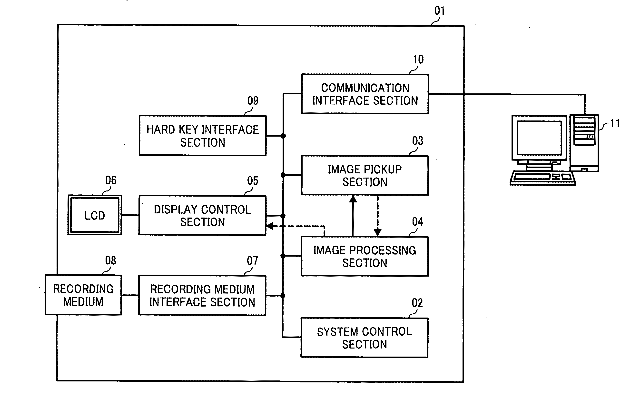
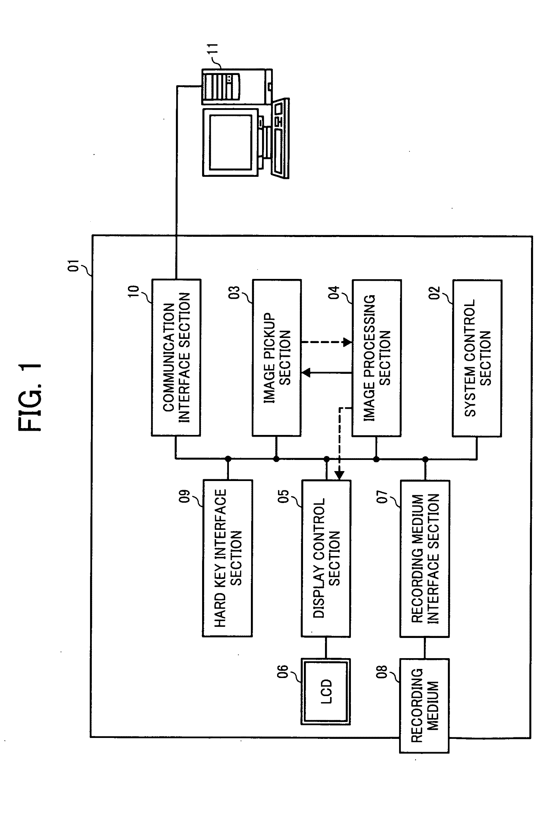
[0016]Preferred embodiments of the present invention will be explained in detail hereinafter with reference to the accompanying drawings. FIG. 1 illustrates a schematic structure of a digital still camera and a configuration of connection devices. In FIG. 1, reference numeral 01 denotes the digital still camera; reference numeral 02 represents a system control section composed of a CPU, a NAND flash memory, a SDRAM, a timer, etc., provided to perform control over the entire digital still camera 01; and reference numeral 03 denotes an image pickup section composed of an optical system component (a lens and a lens drive motor), a CCD, a CCD drive circuit, an A / D converter, etc.

[0017]Reference numeral 04 represents an image processing section, which is composed of a DSP (a digital signal processor) to process an image, a RAM and etc., provided to perform compressing and expanding of the image. The image processing section performs CCD driving timing of the image pickup section 03, zoom...

example 1

[0026]Then, a first example of the present invention will be illustrated when distance information is acquired based on variance in brightness. An operational flow is shown in FIG. 3, wherein operations during the monitoring are illustrated. When the monitor operations begin, the system control section 02 sets a blurring amount parameter described hereinafter to an initial value (=5) (step 01-001). The system control section 02 controls the image processing section 04 and the image pickup section 03, and performs a scanning operation of CCDAF (step 01-002). Then the system control section 02 performs distance determination to each position of each image (step 01-003).

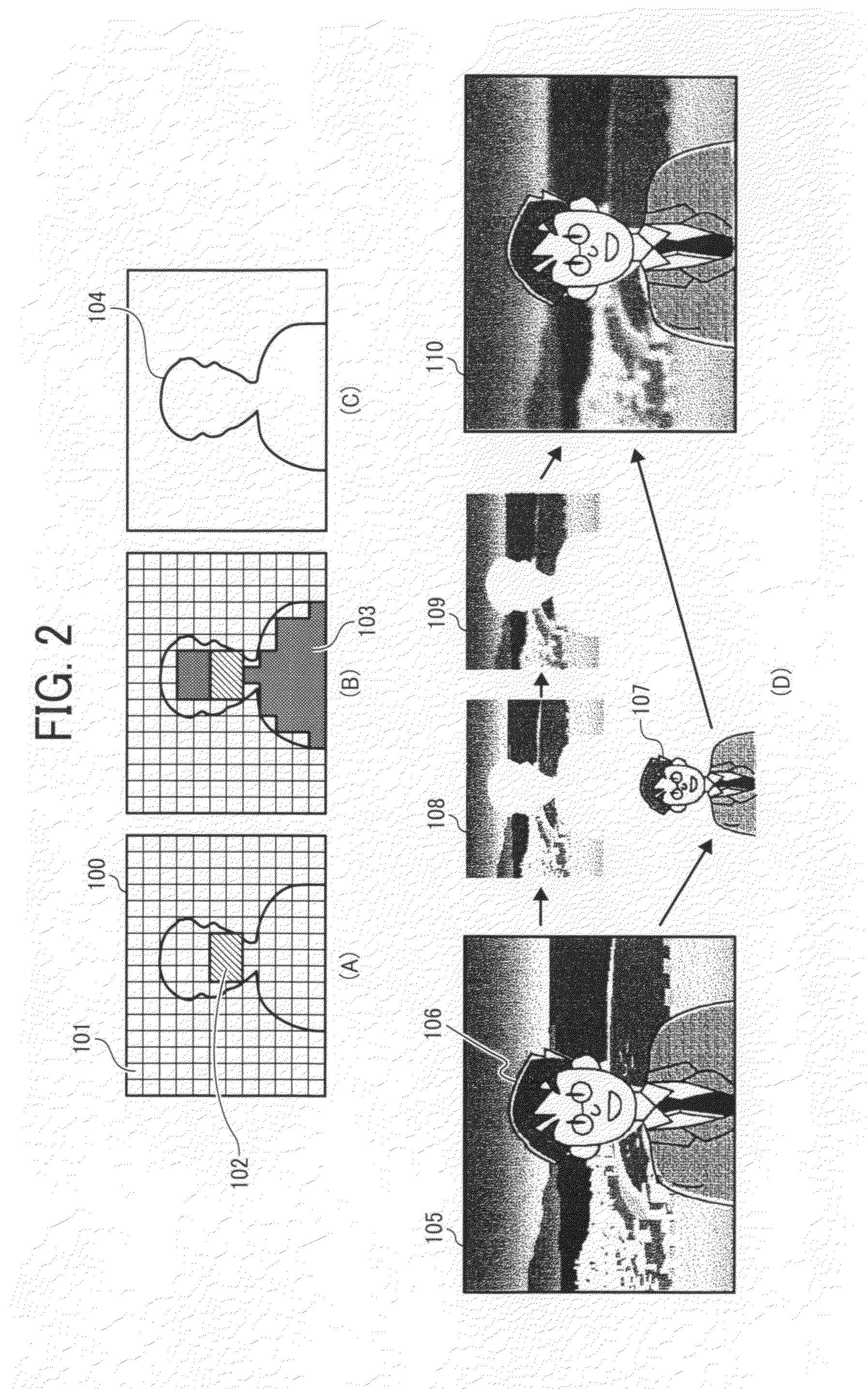
[0027]As illustrated in FIG. 2 (A), reference numeral 100 represents a view angle of a monitoring image and reference numeral 101 denotes one of AF evaluation value areas, which is a small area divided evenly within a range of the view angle of the monitoring image. An AF evaluation value of each of the small areas (an ...

example 2

[0040]Then, another example will be illustrated when the distance information is obtained based on a variation in the pattern. An operational flow is shown in FIG. 4, wherein a processing performed from a step 02-001 to a step 02-005 is the same as that in the step 01. When the determination of the main subject block is completed, the system control section 02 copies the image data of the position corresponding to the main subject block 103 to a work memory within the system control section 02 (see step 02-006). A processing performed from a step 02-007 to a step 02-011 is the same as that in the step 01.

[0041]When the composite image is displayed, the system control section 02 compares the image data corresponding to the position of the main subject block 103 with the data copied to the work memory in the step 02-006. When there exists a difference in excess of a prescribed amount, the system control section 02 shifts to the scanning operation of CCDAF again (see step 02-013).

[0042...


PUM


Abstract

An image pickup device includes a system control section which determines an area with closest proximity as an AF area among AF evaluation areas in a central part of an image. In addition, a block with the same distance as the AF area is determined as a main subject block. Then the system control section calculates and memorizes an average brightness of an image data of a position corresponding to a main subject block. Then, the system control section determines a main subject area based on obtained information on the main subject block and a photographed image. Furthermore, based on information on a main subject area, an extraction processing of the main subject image, a blur processing of a background image and a composite processing are sequentially performed.

Description

CROSS-REFERENCE TO THE RELATED APPLICATION[0001]This application is based on and claims the priority benefit of Japanese Patent Application No. 2007-186553, filed on Jul. 18, 2007, the disclosure of which is incorporated herein by reference in its entirety.BACKGROUND OF THE INVENTION[0002]1. Field of the Invention[0003]The present invention relates to an image pickup device such as a digital still camera provided with a blur processing function and a method for controlling the image pickup device.[0004]2. Description of the Related Art[0005]An image pickup element used in a compact digital camera is smaller both than an image pickup element used in a single-lens reflex camera and a silver-salt film. Therefore, in order to photograph an image with the same view angle, the focal length of a photographic optical system is required to be shorter. Even if the F-number of the photographic optical system is set the same, when the focal length is small, the depth of field becomes greater. A...

Claims


Application Information

Patent Timeline
Patent Type & Authority Applications(United States)
IPC IPC(8): H04N5/228H04N5/225
CPCH04N5/23212H04N5/23248H04N5/23219H04N23/673H04N23/61H04N23/611H04N23/68H04N23/631
Inventor WATANABE, YOSHIKAZU
Owner RICOH KK
Why Eureka
Try Eureka