
Device for Sampling Oral Fluid

a technology for oral fluid and sampling device, which is applied in the separation of components, biochemistry apparatus, sensors, etc., can solve the problems of small amount of oral fluid obtained, high cost, and high labor intensity

Inactive Publication Date: 2009-01-22
INVERNESS MEDICAL SWITZERLAND GMBH
View PDF11 Cites 44 Cited by
  • Summary
  • Abstract
  • Description
  • Claims
  • Application Information

AI Technical Summary

Benefits of technology

The purpose of this invention is to improve how we collect mouth fluid samples for testing.

Problems solved by technology

The technical problem addressed in this patent text is the need for an improved device and method for collecting oral fluids for diagnosis and treatment of infections. Current methods involve using absorbent materials or osmotic absorption, but these methods have limitations and may not provide a representative sample of whole saliva. The invention aims to provide a more efficient and accurate method for collecting oral fluids for analysis.

Method used


Image

  • Device for Sampling Oral Fluid
  • Device for Sampling Oral Fluid

Examples


example 2

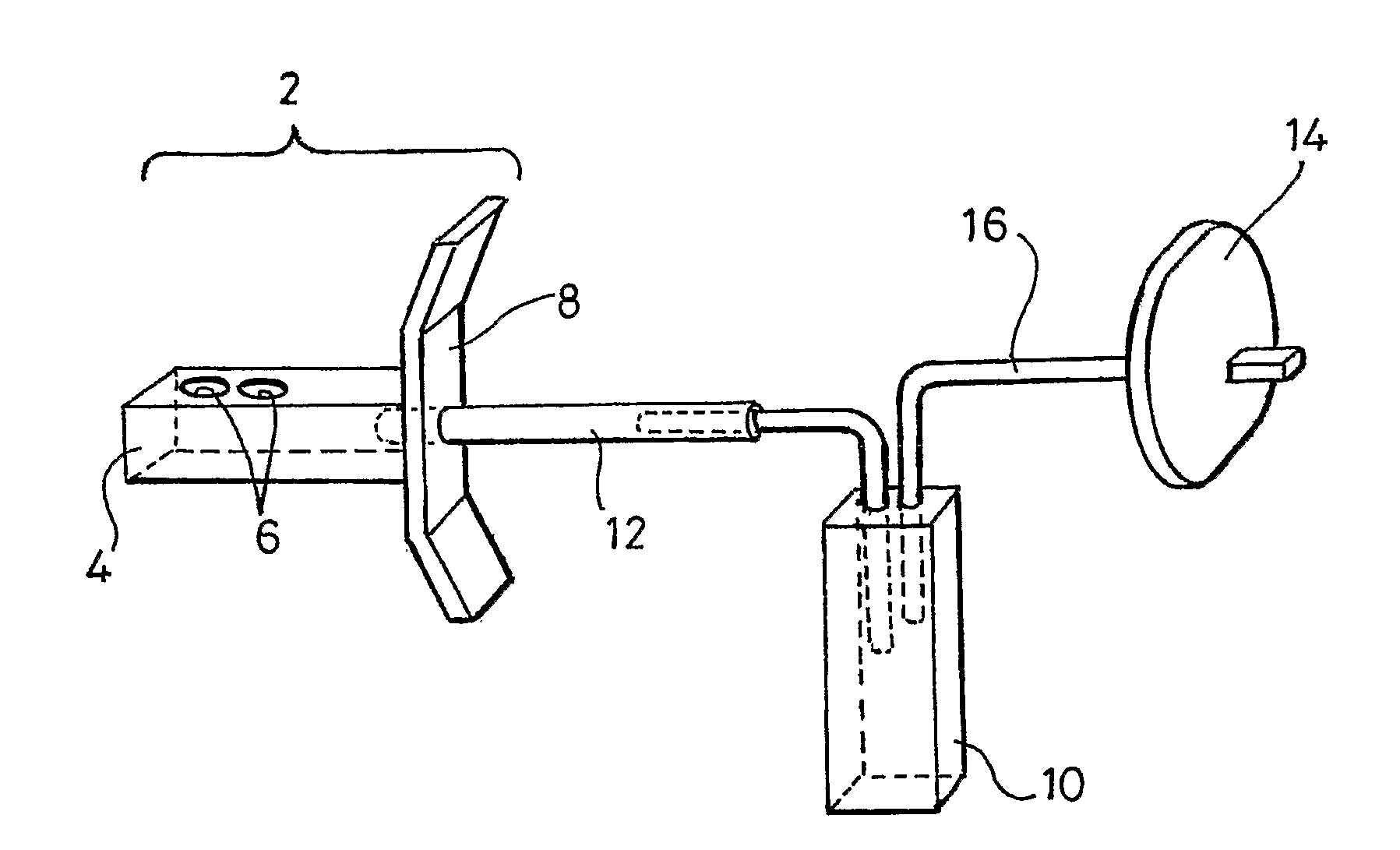
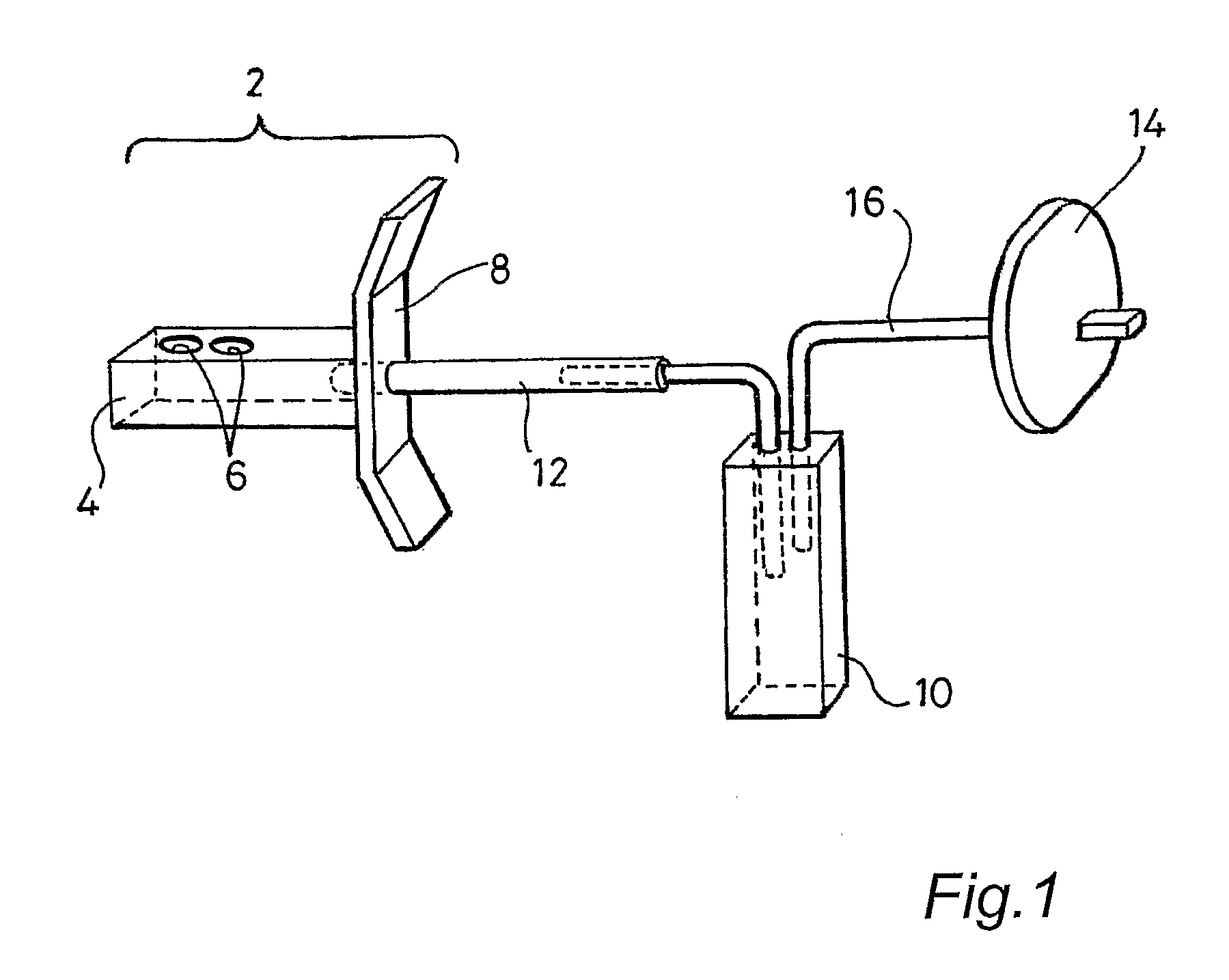
[0054]The present inventors conducted a series of experiments with the aim of determining the optimal location of the sample holes (6) in the wall of the sample collecting chamber (4). In particular, investigations were carried out to determine whether it was preferable for the sample holes (6) to be provided in the upper or lower surface of the wall of the sample collecting chamber (4). Such tests were carried out with ten individual subjects. Each subject was instructed to test three devices having sample holes (6) provided on the upper surface of the wall of the chamber (4) and three devices having sample holes (6) provided on the lower surface of the wall of the chamber (4). The subjects were directed to apply pressure to the chamber (4) for 1 minute. At the end of each test the volume of oral fluid that had been collected was measured (in μl).

[0055]The results of these experiments are presented in Table 1 and demonstrate that samples of oral fluid from the individual subjects w...


PUM


Abstract

A device for the collection of oral fluid from a subject's oral cavity may include a sample-collecting mouthpiece and a one-way valve. The mouthpiece may include a collecting chamber, introducible into the oral cavity of the subject for collecting oral fluid, and a resiliently deformable wall section defining at least part of the collecting chamber such that compression of the resiliently deformable wall forcibly expels a collected fluid from the collecting chamber via a collecting chamber outlet. The one-way valve may be in fluid communication with the collecting chamber outlet and may allow fluid to be displaced from the device following compression of the resiliently deformable wall but prevents ambient air flowing back through the valve into the device.

Description


Claims


Application Information

Patent Timeline
Owner INVERNESS MEDICAL SWITZERLAND GMBH
Learn More