Removable cable gland

Inactive Publication Date: 2009-01-29
COMMSCOPE INC
View PDF15 Cites 40 Cited by
  • Summary
  • Abstract
  • Description
  • Claims
  • Application Information

AI Technical Summary

Benefits of technology

[0010]The Applicants have appreciated one or more dr

Problems solved by technology

This requirement can be particularly troublesome in the case of preterminated cables.
If a field technician is required to install this preterminated fiber optic cable between two female connectors, there is no structure available in the existing art to permit a cable gland to be subsequently installed mid-span of the cable and used along the length of the preterminated cable.
However, this is not an optimum solution in that not all fi

Method used


Image

  • Removable cable gland
  • Removable cable gland
  • Removable cable gland

Examples


Embodiment Construction

[0029]The present invention now is described more fully hereinafter with reference to the accompanying drawings, in which embodiments of the invention are shown. This invention may, however, be embodied in many different forms and should not be construed as limited to the embodiments set forth herein; rather, these embodiments are provided so that this disclosure will be thorough and complete, and will fully convey the scope of the invention to those skilled in the art.

[0030]Like numbers refer to like elements throughout. In the figures, the thickness of certain lines, layers, components, elements or features may be exaggerated for clarity. Broken lines illustrate optional features or operations unless specified otherwise.

[0031]The terminology used herein is for the purpose of describing particular embodiments only and is not intended to be limiting of the invention. Unless otherwise defined, all terms (including technical and scientific terms) used herein have the same meaning as c...


PUM


Abstract

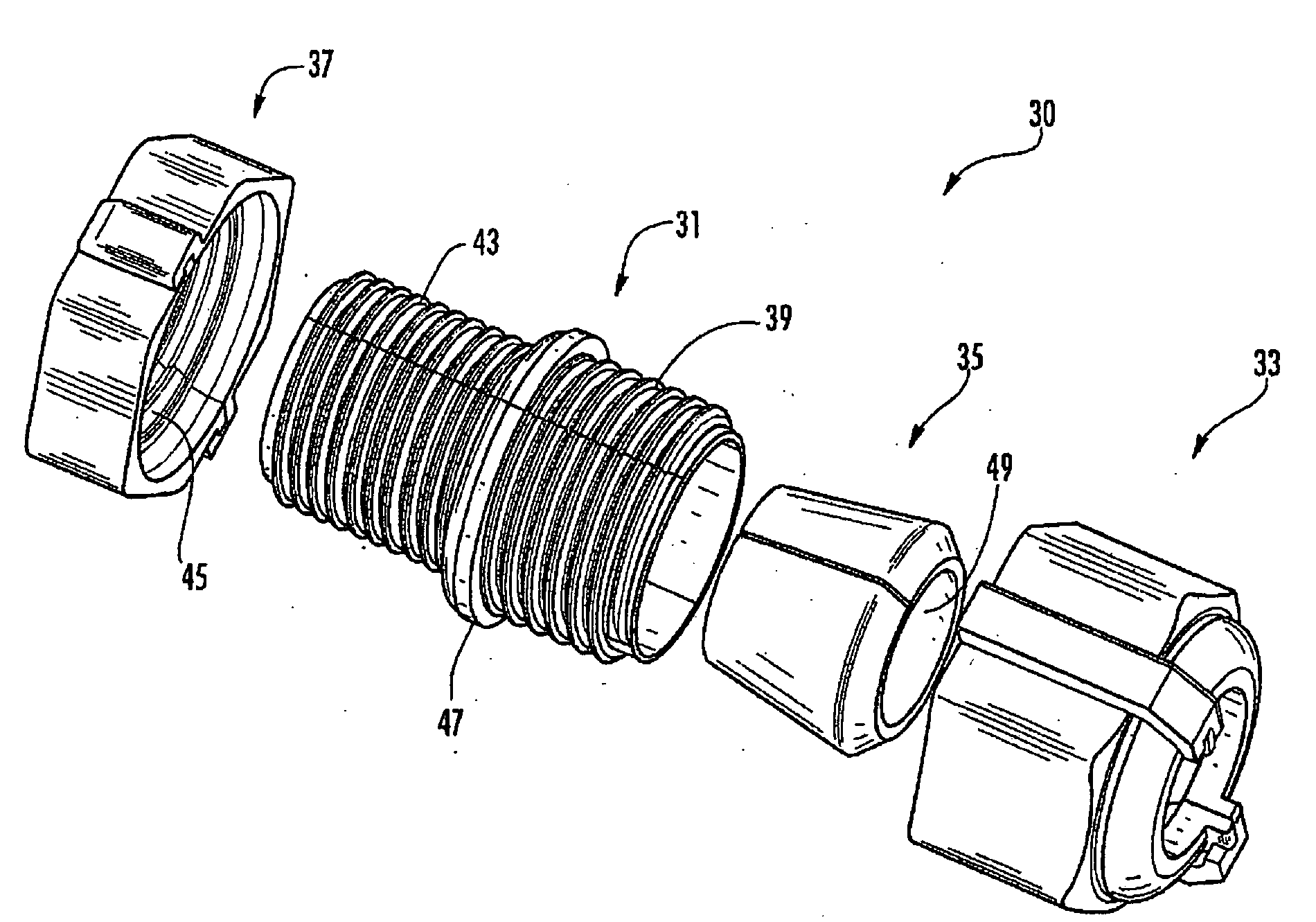
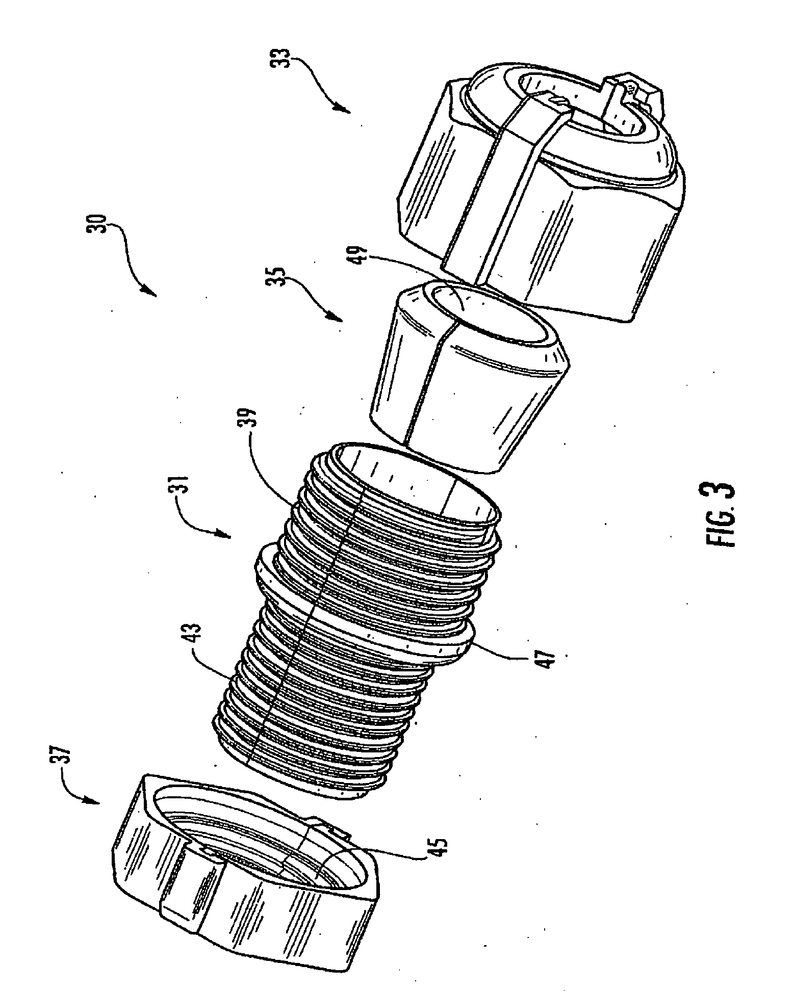
A removable cable gland includes a two-piece fitting which may be laterally assembled over a cable, as opposed to a cable being fed through an opening in the fitting. A two-piece compression nut may also be laterally assembled over the cable. The two pieces of the compression nut are slid together along a longitudinal direction of the cable by a tongue and groove arrangement. The two pieces of the fitting are plugged together in a direction perpendicular to the longitudinal direction of the cable. Once first threads of the fitting are engaged to second threads of the compression nut, the two-piece fitting is locked together by the surrounding compression nut. Simultaneously, the two-piece compression nut is locked together, such that the tongue may not slide longitudinally relative to the groove, due to the first and second thread engagement.

Description

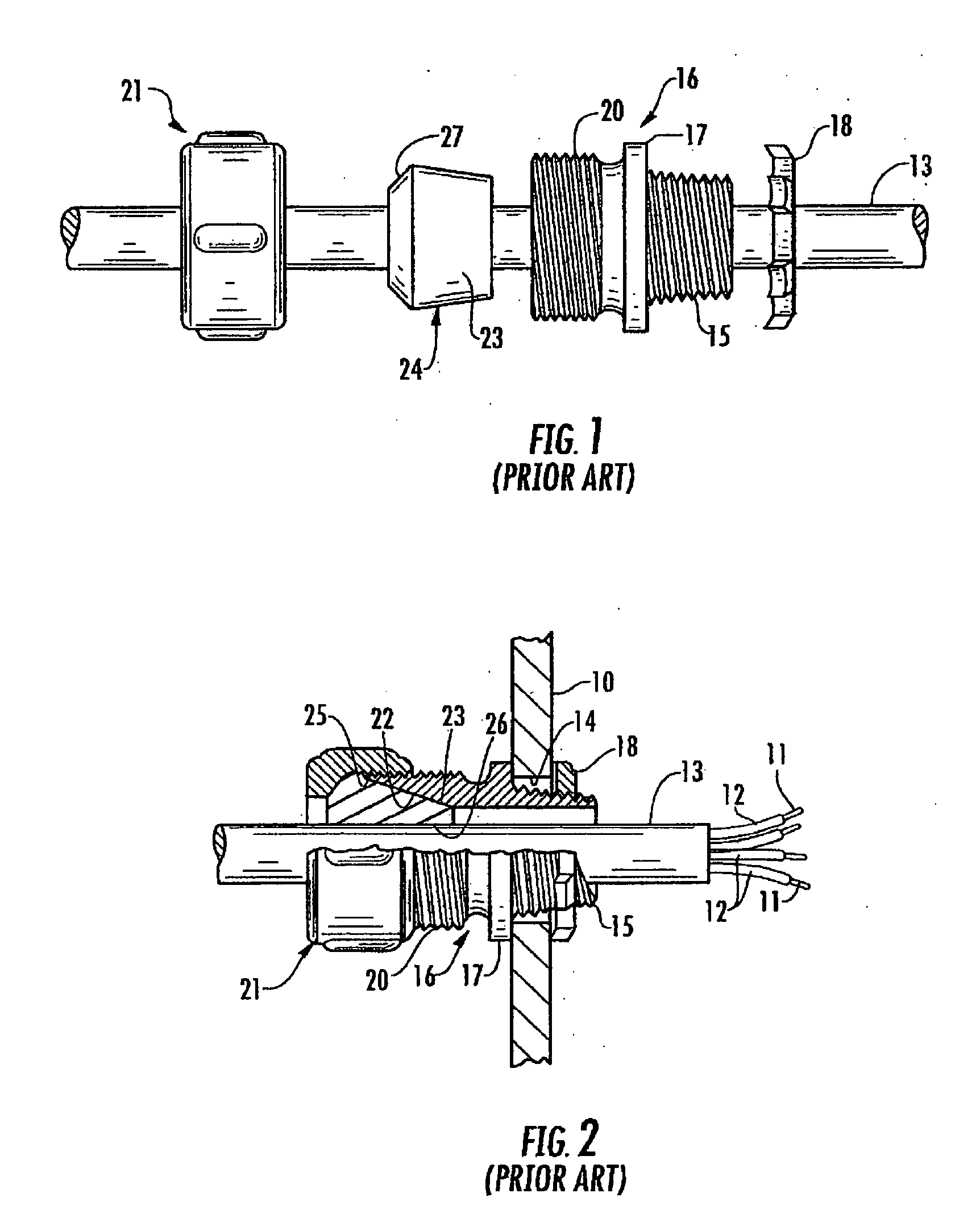
BACKGROUND OF THE INVENTION[0001]1. Field of the Invention[0002]The present invention relates to a cable gland, which may be employed on fiber optic cables, coaxial cables, twisted pair cables, or other types of cables or elongated objects. More particularly, the present invention relates to a cable gland having a two-piece fitting and two-piece compression nut, which can be assembled around any portion of a cable.[0003]2. Description of the Related Art[0004]Cable glands are well known in the existing arts. A cable gland is generally a structure which is mechanically fixed to an outer jacket of a cable, typically by a frictional fit or possibly an adhesive. The cable gland also has attachment features which allow the cable gland to be attached to a secondary object, such as a housing, plate, or guide. The cable gland thereby provides strain relief to the cable. In other words, a pulling force applied to the cable's jacket will be transmitted, via the jacket, to the cable gland and h...

Claims


Application Information

Patent Timeline
IPC IPC(8): H02G15/007
CPCH02G3/0675
Inventor ANDERSON, TIMOTHY W.CASE, RICHARD L.CRAIN, THOMASLIVINGSTON, JOSEPH C.RUIZ, GILWOMACK, WADE
Owner COMMSCOPE INC
Why Eureka
Try Eureka