Symbol timing recovery circuit

a recovery circuit and symbol technology, applied in the field of symbol timing recovery circuits, can solve the problems of ber (bit error rate) characteristics deteriorating, and the recovery accuracy of symbol timing being affected

Active Publication Date: 2009-01-29
FUJITSU SEMICON MEMORY SOLUTION LTD
View PDF5 Cites 28 Cited by
  • Summary
  • Abstract
  • Description
  • Claims
  • Application Information

AI Technical Summary

Problems solved by technology

The sideband wave causes deterioration of recovery accuracy of the symbol timing.
The deterioration of recovery accuracy of the symbol timing would cause deterioration of BER (Bit Error Rate) characteristics.

Method used


Image

  • Symbol timing recovery circuit
  • Symbol timing recovery circuit
  • Symbol timing recovery circuit

Examples


Embodiment Construction

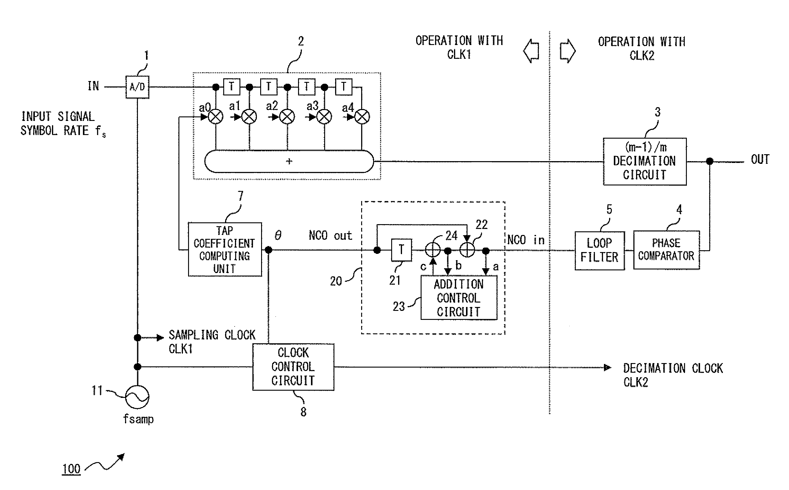
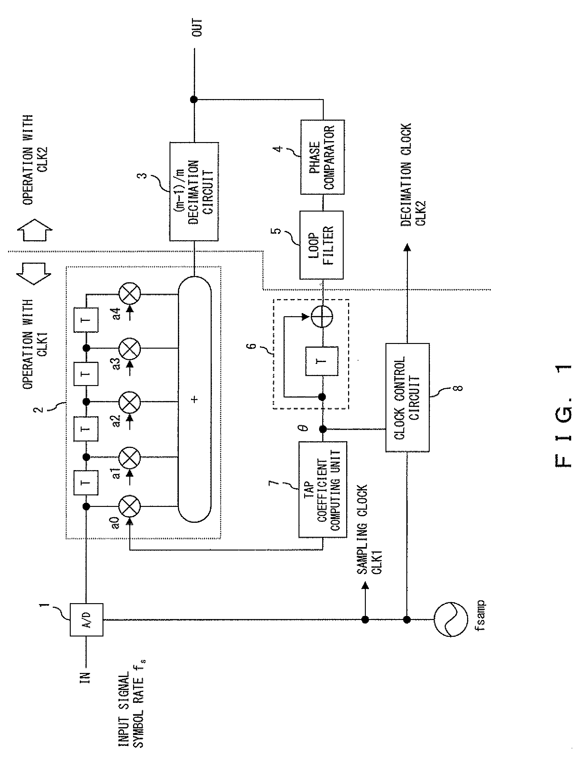
[0029]In a symbol timing recovery circuit on the embodiment, when the frequency of the first clock does not match the frequency twice as high as the symbol rate of the input signal, the phase of the sampled data obtained by the sampling unit gradually shifts. The numerically controlled oscillator calculates the phase shift, and the interpolation unit performs interpolation in accordance with the calculated phase shift. When the above frequencies do not match, data decimation is performed in accordance with the difference in the frequencies. At the timing of the decimation, the calculated value of the numerically controlled oscillator is adjusted for an amount in accordance with the data decimation. Here, the data decimated by the decimation unit is the same as the immediately previous data. In this adjustment, because the output value of the loop filter is subtracted, the phase represented by the calculated value of the numerically controlled oscillator should be the same in immedia...


PUM


Abstract

An A / D converter samples an input signal with a first clock. An FIR filter generates data at a zero-crossing point / data decision point from the sampled data. A decimation circuit decimates an output of the FIR filter 2 with a second clock. A phase comparator detects a phase error of the output signal of the decimation circuit. An NCO generates a phase signal by integrating the phase error. A tap coefficient computing unit generates tap coefficients of the FIR filter in accordance with the phase signal. In the NCO, if the phase signal exceeds “π”, “2π+ the phase error” is subtracted from the phase signal.

Description

CROSS REFERENCE TO RELATED APPLICATION[0001]This application is based upon and claims the benefit of priority from the prior Japanese Patent Application No. 2007-193071, filed on Jul. 25, 2007, the entire contents of which are incorporated herein by reference.BACKGROUND OF THE INVENTION[0002]1. Field of the Invention[0003]The present invention relates to a symbol timing recovery circuit that recovers the symbol timing of an input signal.[0004]2. Description of the Related Art[0005]In general, recovery of a received signal in a communication system requires recovery of the symbol timing from the received signal. In the following description, a symbol timing recovery circuit described in Patent Document 1 (Japanese Patent No. 3573627) is explained with reference to FIG. 1.[0006]In FIG. 1, an A / D converter 1 converts an input signal (or a received signal) into a digital signal. The sampling rate of the A / D converter 1, fsamp, is the same or more than twice as fast as the symbol rate of...

Claims


Application Information

Patent Timeline
Patent Type & Authority Applications(United States)
IPC IPC(8): H04L7/00
CPCH04L7/0334H04L7/0029
Inventor KITTA, TATSUAKI
Owner FUJITSU SEMICON MEMORY SOLUTION LTD
Why Eureka
Try Eureka