
Inertial navigation system error correction

a technology of error correction and navigation system, applied in navigation, instruments, surveying and navigation, etc., can solve the problems of same types of angular errors, and small angular tilt errors

Active Publication Date: 2009-02-05
NORTHROP GRUMMAN GUIDANCE & ELECTRONICS +1
View PDF14 Cites 21 Cited by
  • Summary
  • Abstract
  • Description
  • Claims
  • Application Information

AI Technical Summary

Problems solved by technology

Again small angular errors will exist in achieving alignment of the Instrument Coordinate Frame, FA, with the axes of the Inertial Coordinate Frame, FI, due to errors in the measurements made by the inertial instruments.
For the strapdown mechanization referred to above, these same types of angular errors will occur due to inertial instrument measurement errors.
In either the strapdown or gimbaled inertial instrument mechanizations, small angular tilt errors [φE, φN, φZ], will exist due to the errors in the measurement made by the gyros and accelerometers.
However due to errors in the gyro and accelerometer measurements, the error in realizing the ideal situation for the gimbaled case is expressed by the matrix [I+φ].

Method used


Image

  • Inertial navigation system error correction
  • Inertial navigation system error correction
  • Inertial navigation system error correction

Examples


Embodiment Construction

[0036]Reference will now be made to the preferred embodiments of the invention, examples of which are illustrated in the accompanying drawings. While the invention will be described in conjunction with the preferred embodiments, it will be understood that these embodiments are not intended to limit the invention. On the contrary, the invention is intended to cover alternatives, modifications and equivalents, which may be included within the spirit and scope of the invention as defined by the appended claims.

[0037]In the following detailed description, numerous specific details are set forth in order to provide a thorough understanding of the present invention. However, it will be understood by one of ordinary skill in the art that the present invention may be practiced without these specific details. In other instances, well known methods, procedures, components, and circuits have not been described in detail so as not to unnecessarily obscure the important aspects of the present in...


PUM


Abstract

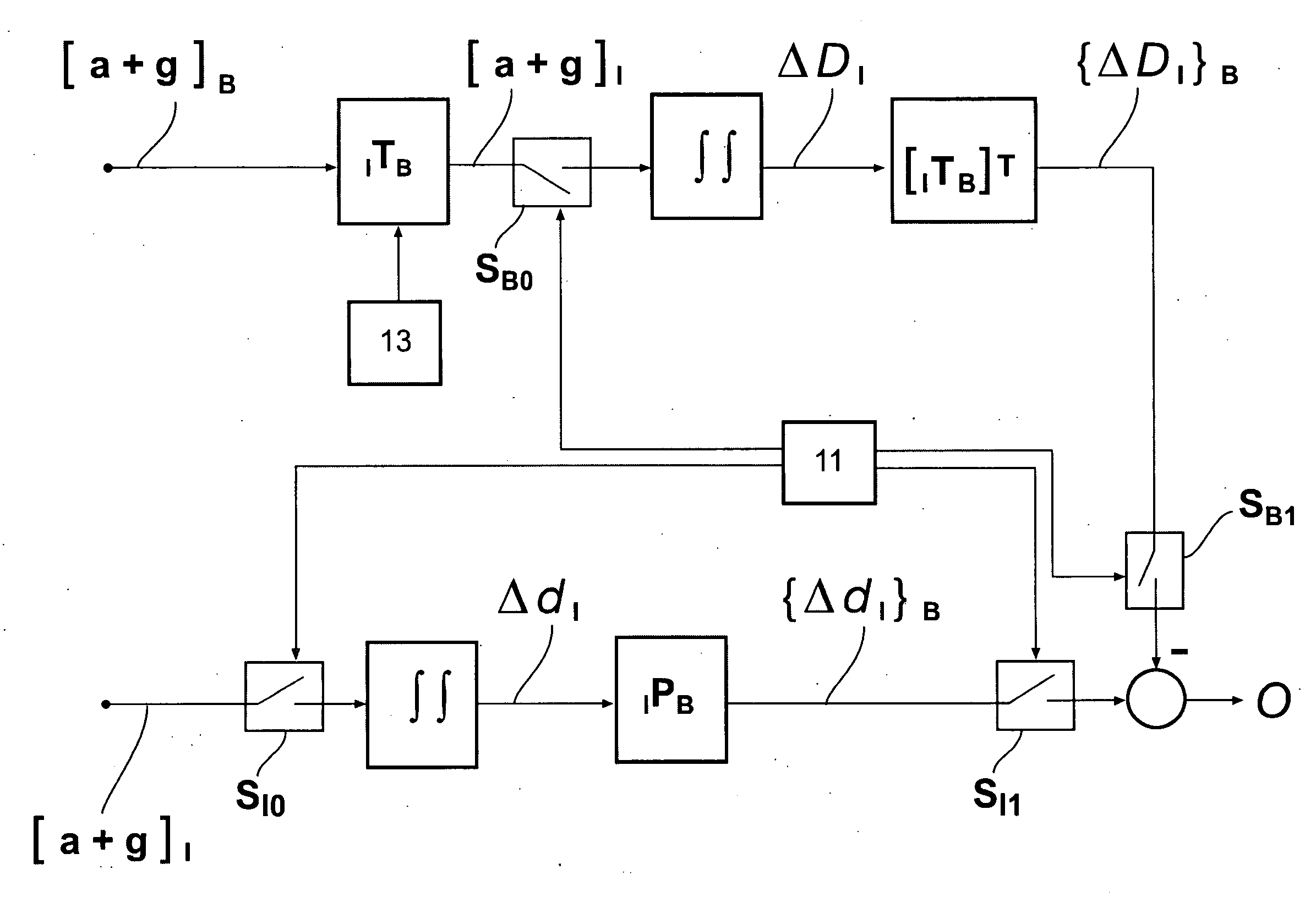
Methods and apparatus for: (a) the correction of one or more elements determined from a first set of continuous gyro and accelerometer measurements comprising using a second set of discontinuously measured higher accuracy accelerometer measurements doubly integrated in an inertial coordinate system, (b) determining relative movement of a vehicle using a first set of acceleration measurements that do not include components of acceleration caused by the Earth's gravitational field, and a second set of acceleration measurements that do include components of acceleration caused by the Earth's gravitational field; and (c) correcting errors in an inertial navigation system positioned in a vehicle comprising using independently measured changes in position of the vehicle relative to an inertial coordinate frame.

Description

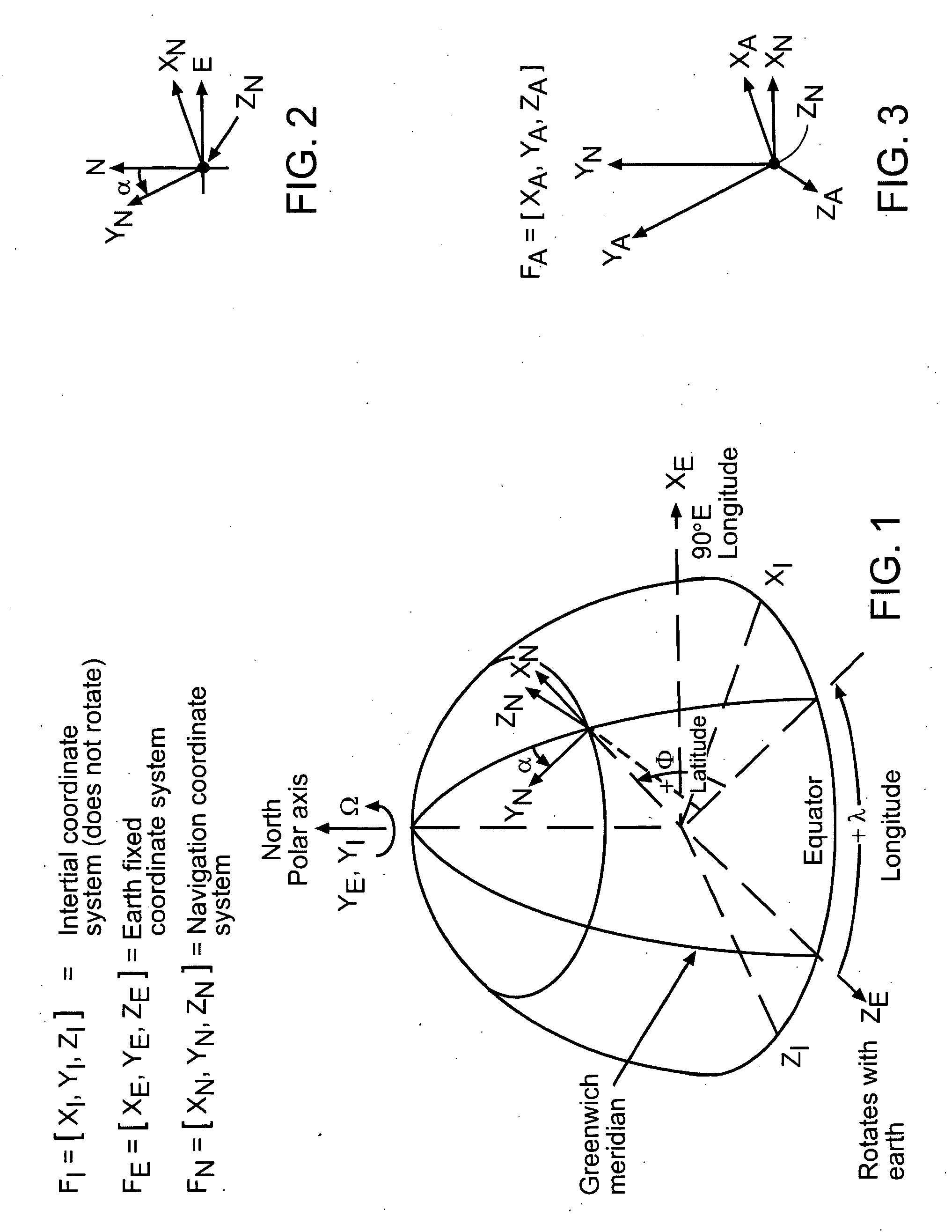
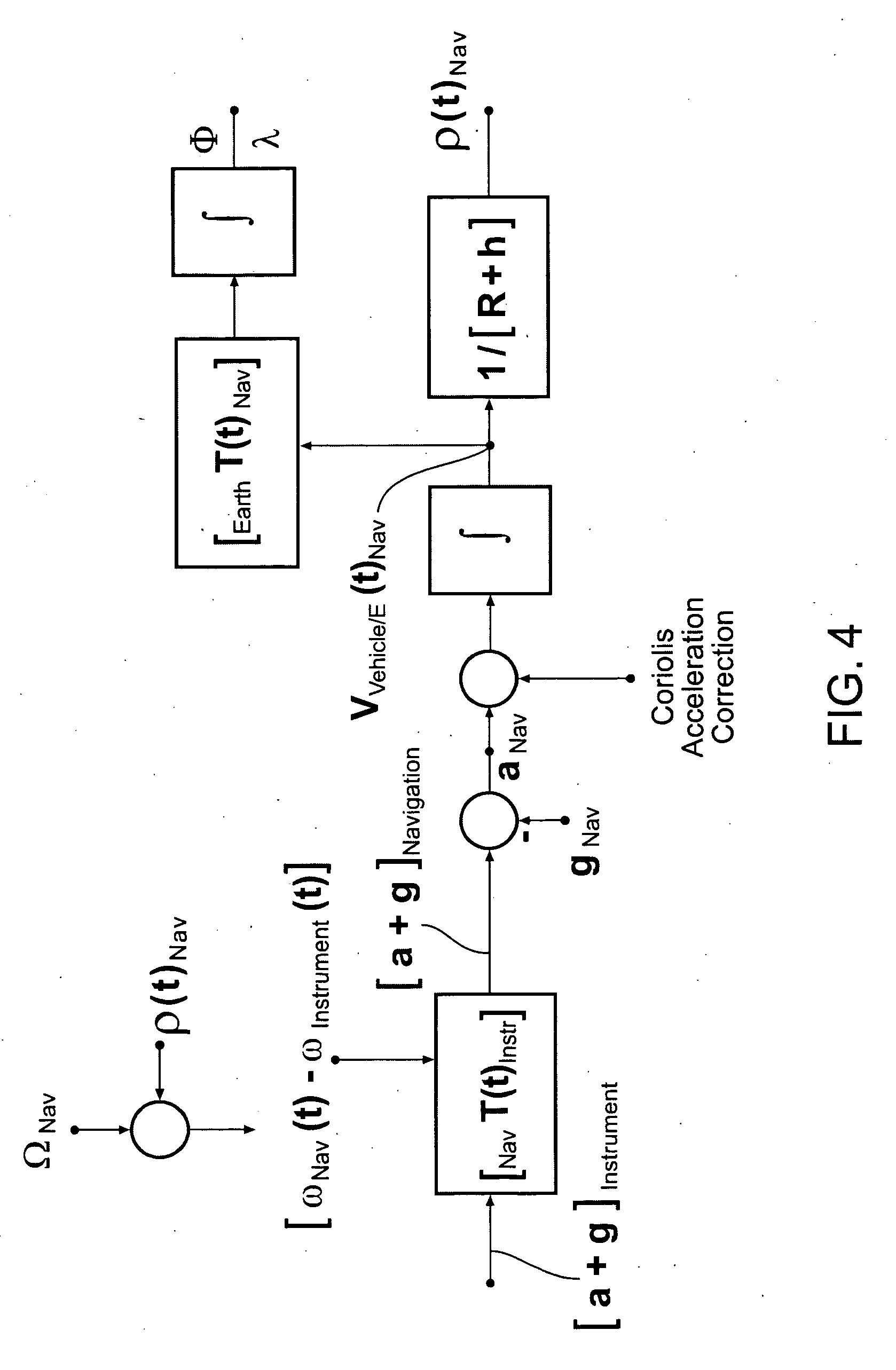
CROSS-REFERENCES TO RELATED APPLICATIONS[0001]This application claims the benefit of Provisional Application No. 60 / 557,065, filed Mar. 29, 2004, herein incorporated by reference in its entirety.STATEMENT REGARDING FEDERALLY SPONSORED RESEARCH[0002]The U.S. Government has a paid-up license in this invention and the right in limited circumstances to require the patent owner to license others on reasonable terms as provided for by the terms of Grant No. W911NF-04-1-0047 awarded by the Defense Advanced Research Projects Agency (DARPA).FIELD OF THE INVENTION[0003]The present invention relates generally to inertial navigation system error correction.BACKGROUND OF THE INVENTION[0004]FIG. 1 defines three orthogonal coordinate frames, FI, FE, and FN. The first coordinate frame, FI, is called the Inertial Coordinate Frame with axes [XI, YI, ZI] that are fixed with respect to inertial space as represented for example by stellar bodies. The XI and ZI axes of this coordinate frame lie nominally...

Claims


Application Information

Patent Timeline
Patent Type & Authority Applications(United States)
IPC IPC(8): G01C21/00G01C21/10G01C21/16G01C25/00G01S19/53G08G1/0969
CPCG01C25/005G01C21/16G01C21/185G01C21/188
Inventor HUDDLE, JAMES R.
Owner NORTHROP GRUMMAN GUIDANCE & ELECTRONICS
Learn More