
Firearm handgrip with a horizontal angle tracking bipod

a technology of horizontal angle tracking and handgrip, which is applied in the field of handgrips with bipods, can solve the problems of manual stabilization of firearms and impracticality of simply holding them tight, and achieve the effect of fast deployment and highly reliable release mechanism

Inactive Publication Date: 2009-02-12
OZ MOSHE
View PDF11 Cites 31 Cited by
  • Summary
  • Abstract
  • Description
  • Claims
  • Application Information

AI Technical Summary

Benefits of technology

[0009]The present invention discloses a firearm handgrip with a collapsible and concealable bipod positioned within the handgrip. The bipod enables tracking of the horizontal angle of the firearm. Specifically, the bipod is quickly deployable by pressing a button that activates a highly reliable release mechanism. Upon bipod deployment, the shooter is free to place the bipod on any surface, including uneven surfaces wherein the bipod legs are positioned on different heights so that the bipod maintains stability. The bipod enables panning (horizontal rotation) and canting (right-left) of the firearm. Additionally, after panning the firearm and subsequently lifting the bipod from the surface it lies on, the bipod's legs automatically realign to a plane perpendicular to the firearm, thus tracking and adjusting to the new horizontal angle of the firearm.

Problems solved by technology

Stabilizing the firearm manually, simply by holding it tight is usually impractical due to the size and weight of the firearm.
Specifically, locking the bipod prevents the abovementioned motions (panning, tilting canting) and therefore the suggested bipod is limited to shooting activities where these motions are not required.

Method used


Image

  • Firearm handgrip with a horizontal angle tracking bipod
  • Firearm handgrip with a horizontal angle tracking bipod
  • Firearm handgrip with a horizontal angle tracking bipod

Examples


Embodiment Construction

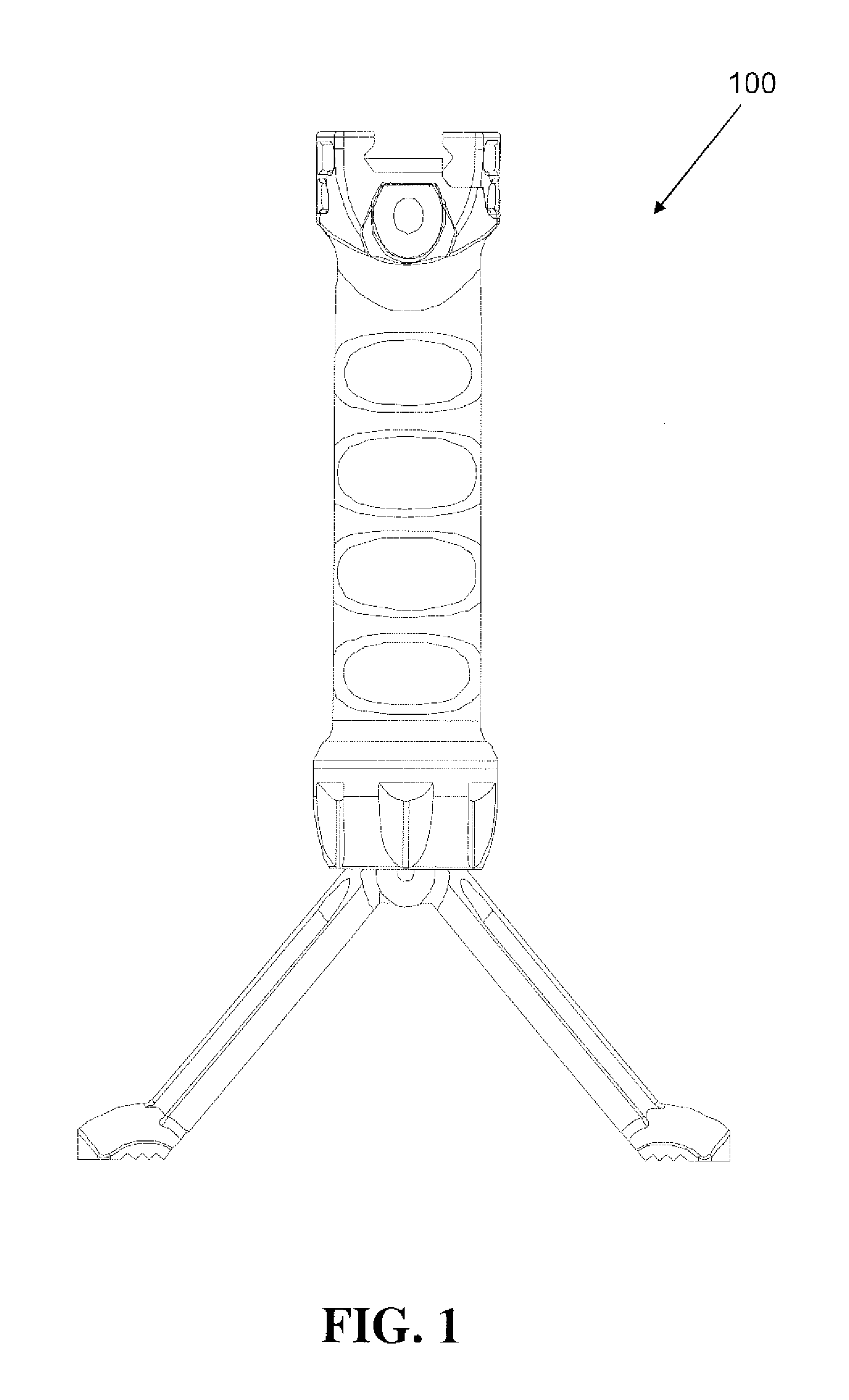
[0018]FIG. 1 shows an elevational view of an embodiment of the invention showing the firearm handgrip 100 with the bipod in after deployment 101. The handgrip 100 enables the shooter to practice all the motions required in combat. Specifically, the handgrip 100 may be horizontally rotated around its axis in a panning motion l102. Finally, the handgrip 100 may be canted to the right 103B and to the left 103A in order to fit the bipod to an uneven support surface.

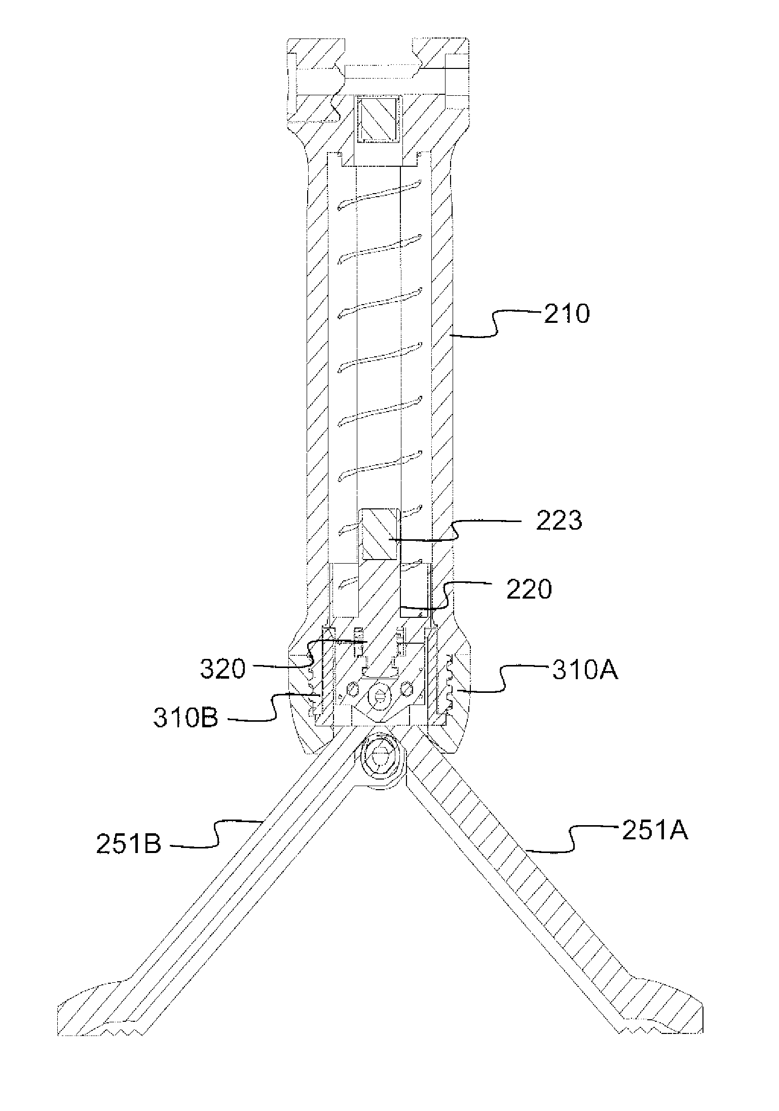
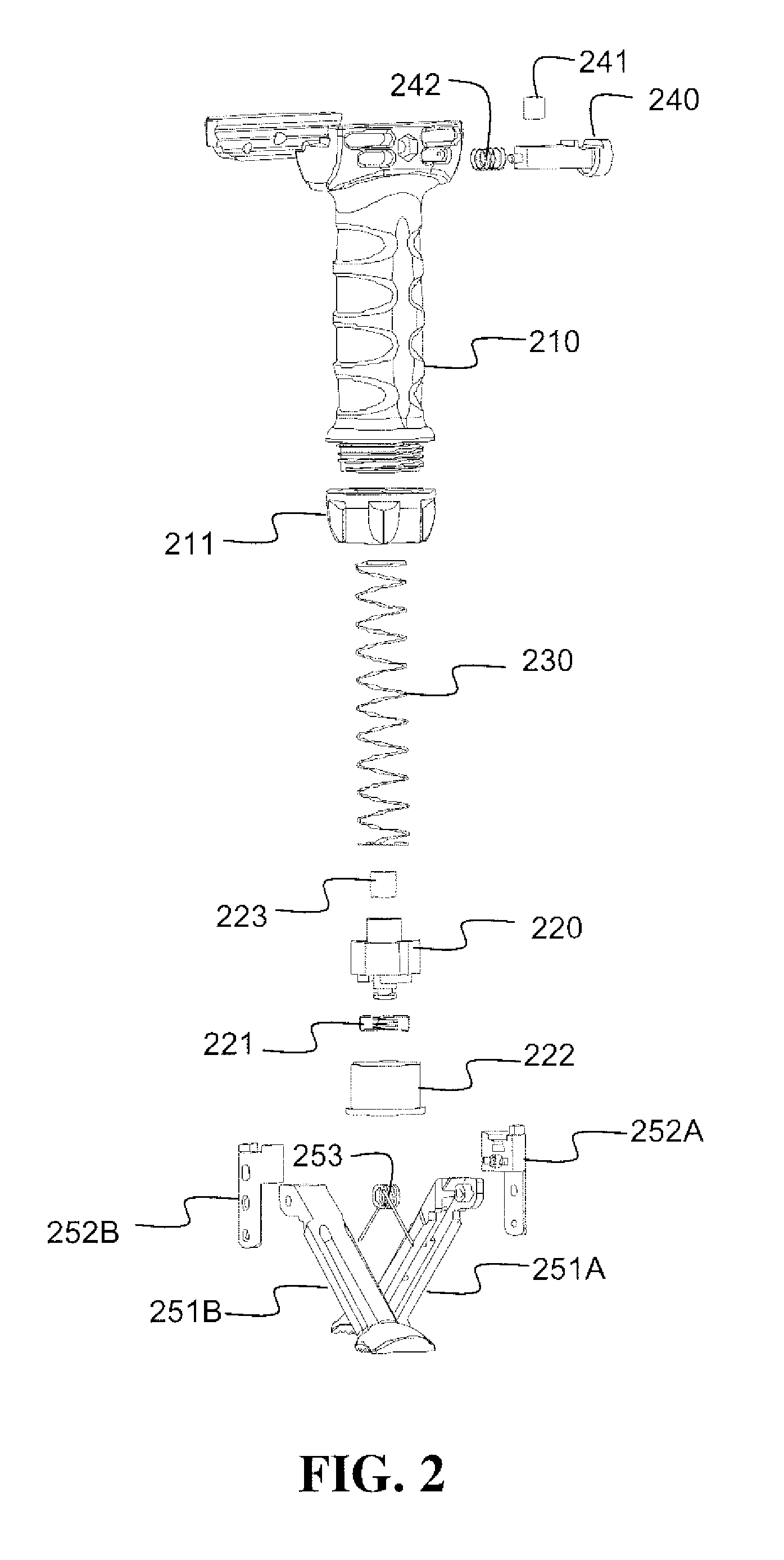
[0019]FIG. 2 shows an exploded view of an embodiment of the invention showing the firearm handgrip 100. The handgrip 100 comprises a hollow housing 210 mountable to a firearm. The housing 210 has a top end with a horizontal channel and an open bottom end. The handgrip 100 further comprises a bipod comprising a vertically sliding piston 220 located within the housing 210. The piston 220 has a top end and a bottom end. The handgrip 100 further comprises two legs 252A, 252B hingedly connected to the bottom end of said piston 220...


PUM


Abstract

A firearm handgrip with a collapsible and concealable bipod positioned within the handgrip. The bipod enables tracking of the horizontal angle of the firearm. Specifically, the bipod is quickly deployable by pressing a button that activates a highly reliable release mechanism. Upon bipod deployment, the shooter is free to place the bipod on any surface, including uneven surfaces wherein the bipod legs are positioned on different heights so that the bipod maintains stability. The bipod enables panning (horizontal rotation), tilting (up-down) and canting (right-left) of the firearm. Additionally, after panning the firearm and subsequently lifting the bipod from the surface it lies on, the bipod's legs automatically realign to a plane perpendicular to the firearm, thus tracking and adjusting to the new horizontal angle of the firearm.

Description

FIELD OF THE INVENTION [0001]The present invention relates generally to firearm accessories and more specifically to a firearm handgrip with a bipod.BACKGROUND OF THE INVENTION[0002]Shooting firearms, specifically during combat requires maintaining a steady and stable position to insure accuracy of aim. Stabilizing the firearm manually, simply by holding it tight is usually impractical due to the size and weight of the firearm. Therefore, peripheral support devices have been developed during the years for use in conjunction with firearms as a means for stabilizing and improving accuracy.[0003]Early stabilizing means were large stationary objects such as rocks and tree branches to forked sticks, shooting slings, bipods and tripods. In more recent times, compact collapsible bipod supports have been developed. These collapsible bipods are relatively lightweight and are mountable to the forearm stock of a firearm. Most conventional bipod supports include a pair of legs that can be pivot...

Claims


Application Information

Patent Timeline
Patent Type & Authority Applications(United States)
IPC IPC(8): F41C27/20
CPCF41A23/10
Inventor OZ, MOSHE
Owner OZ MOSHE
Learn More