
Photovoltaic power apparatus for rapid deployment

Inactive Publication Date: 2015-06-11
COWHAM WALTER
View PDF3 Cites 18 Cited by
  • Summary
  • Abstract
  • Description
  • Claims
  • Application Information

AI Technical Summary

Benefits of technology

The present invention is a standalone power system that has a rapidly deployable PV array. It is designed to be easily moved and redeployed in another location. The system is self-contained and can reach remote locations that are not normally served by an electrical grid. It is also versatile and adaptable to emergency situations. The technical effects of this system are its ease of deployment, robustness, and ability to address remote or emergency locations.

Problems solved by technology

While the above examples of standalone power systems provide improvements on prior technology, they do so at a cost of complexity and related unreliability.

Method used


Image

  • Photovoltaic power apparatus for rapid deployment
  • Photovoltaic power apparatus for rapid deployment
  • Photovoltaic power apparatus for rapid deployment

Examples


Embodiment Construction

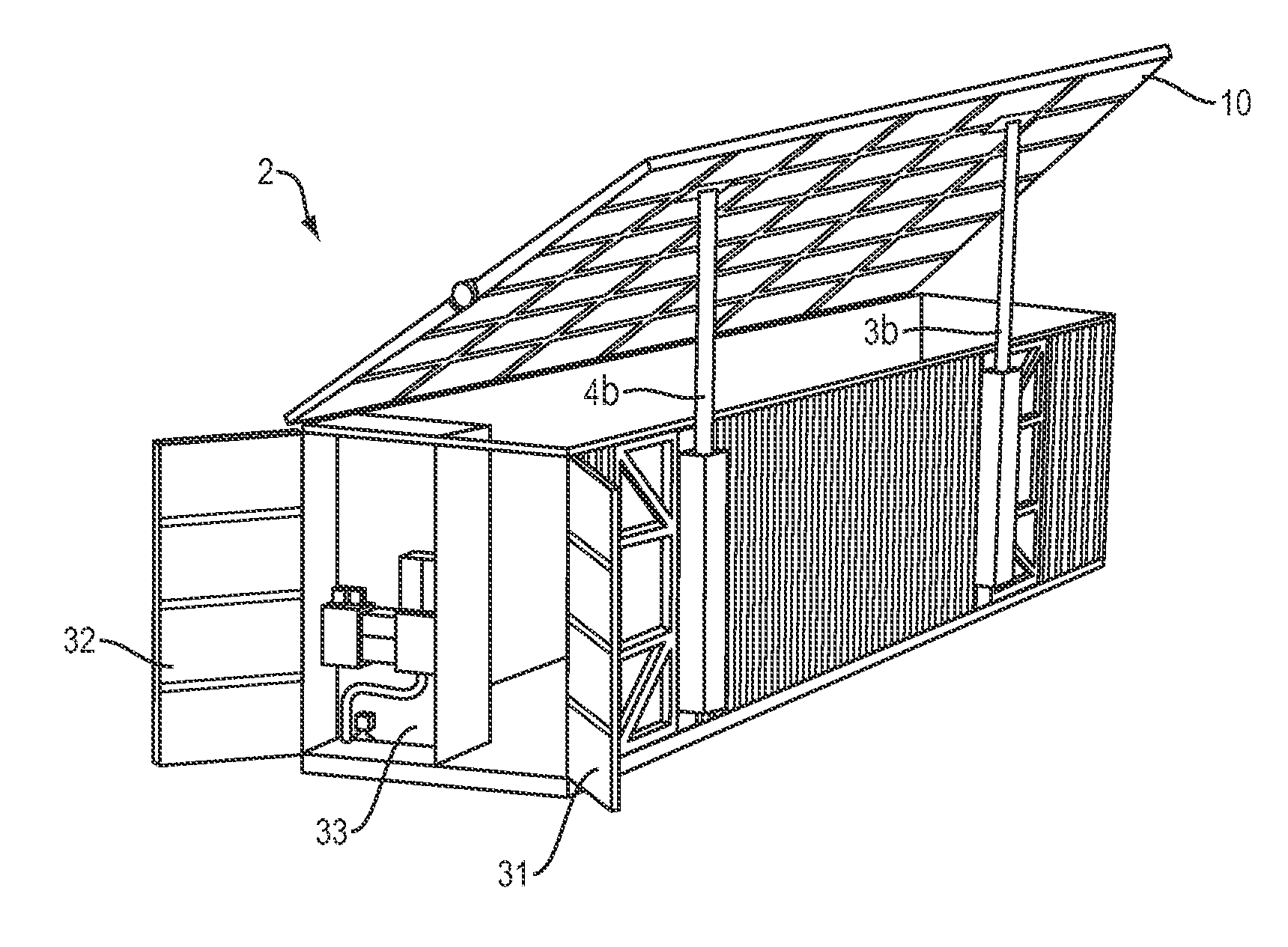
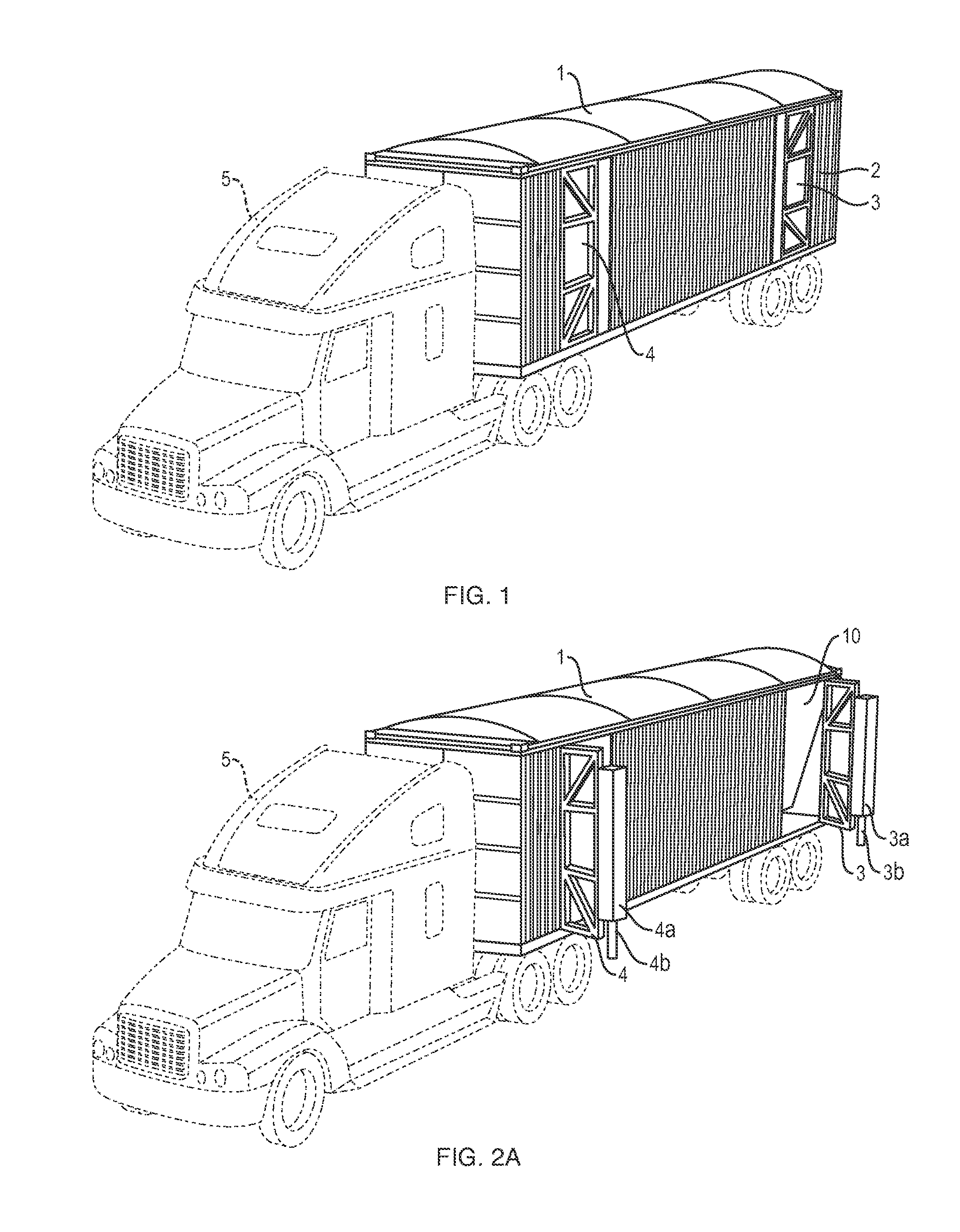
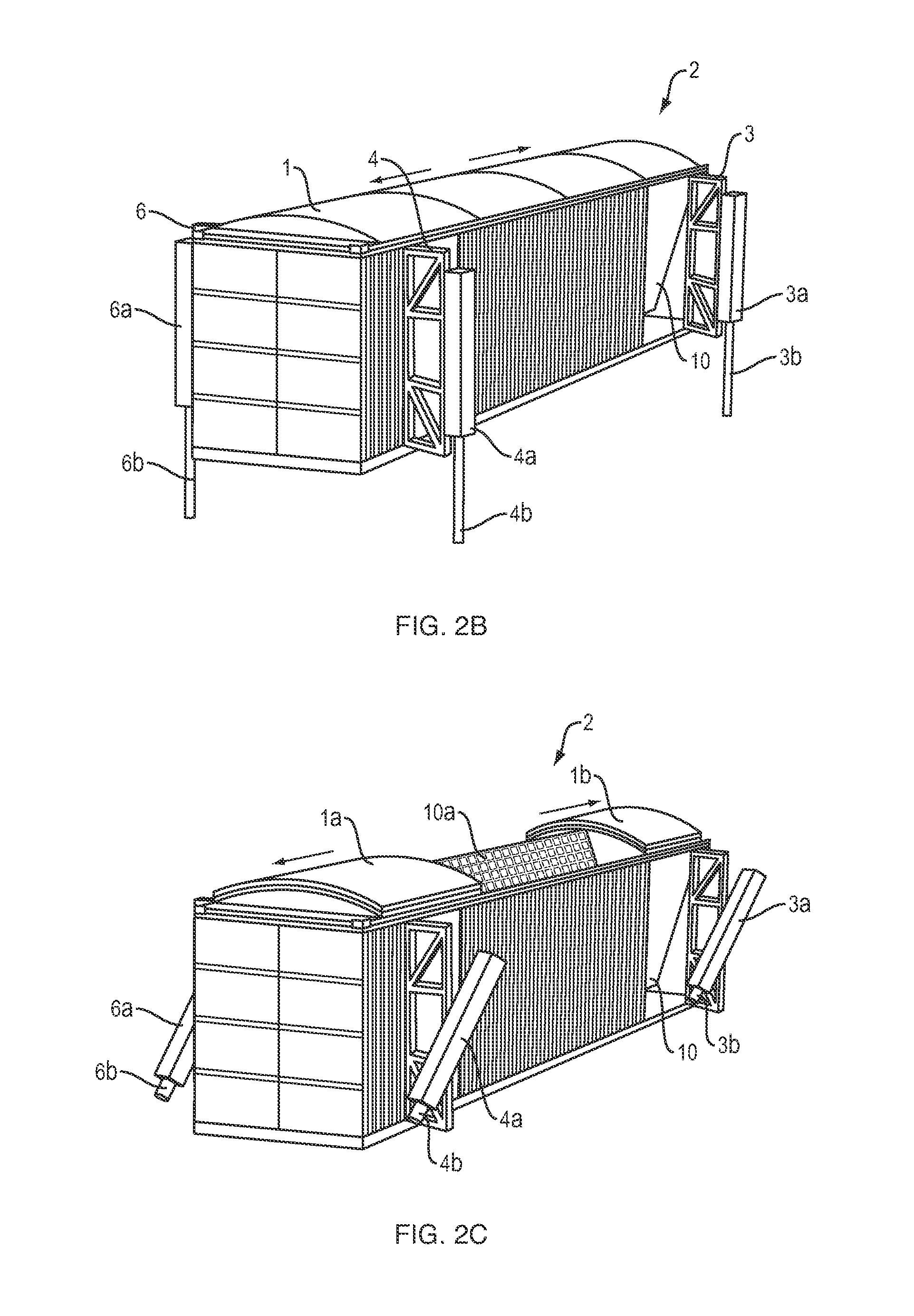
[0032]In general, the present invention includes three primary elements including a housing, a PV array, and electrical components to obtain useful electrical output from the PV array and provide such output as an electrical supply used, for example, in nearby housing. These three general elements will now be discussed in further detail.

[0033]The housing is preferably formed from a standardized steel shipping container or a custom-built container from an original equipment manufacturer (OEM) capable of adherence to the standards promulgated by the International Organization for Standardization (ISO). Whether the housing is a customized ISO container or an OEM container explicitly manufactured for the present invention is a matter of cost and availability. One useful and important aspect of the present invention is the ubiquitous nature of ISO container in the freight shipping industry. One need not go far to stumble upon an unused or underutilized ISO container. Indeed, such ISO con...


PUM


Abstract

A rapidly deployed photovoltaic (PV) apparatus (2) providing a PV array (10) housed within an easily transportable standardized container. The PV array (10) is movable between a stowed position in a V-shape configuration and a fully deployed flat position. Dual function hydraulic cylinders are provided for movement of the array (10) in the fully deployed position and movement of the container when the array (10) is in the stowed position. Solar tracking of the array (10) is facilitated by linear compensation translators which are attachable to the hydraulic cylinders upon full deployment. A retractable roof structure is provided which allows trickle charging to occur when the array (10) is in the V-shaped stowed position.

Description

CROSS REFERENCE TO RELATED APPLICATIONS[0001]This application is a continuation of Application No. PCT / US14 / 65852 filed on 16 Nov. 2014 which claims priority from U.S. provisional application Ser. No. 61 / 905,817 filed 18 Nov. 2013, the contents of which are herein incorporated by reference.FIELD OF THE INVENTION[0002]The present invention relates generally to photovoltaic power generation. More particularly, the present invention relates to photovoltaic power systems for rapid deployment, portability, and redeployment.BACKGROUND OF THE INVENTION[0003]In the field of power generation, there are many examples of standalone systems not tied to the power grid. Such standalone systems often involve a generator fueled by a hydrocarbon-based fuel such as gasoline, diesel, or propane. However, some such systems are wind or solar powered in terms of a blade driven rotary turbine or photovoltaic array, respectively. Still further, some such systems function through a combination of wind, sola...

Claims


Application Information

Patent Timeline
IPC IPC(8): H02S10/40H02S30/20H02J7/00
CPCH02S10/40H02S30/20H02J7/0042F24S25/70F24S2025/012F24S2030/115Y02B10/10Y02E10/47Y02E10/50
Inventor COWHAM, WALTER
Owner COWHAM WALTER
Learn More