Shock-resisting device and method

Active Publication Date: 2017-10-12
RAYTHEON CO
View PDF2 Cites 19 Cited by
  • Summary
  • Abstract
  • Description
  • Claims
  • Application Information

AI Technical Summary

Benefits of technology

[0003]The present disclosure provides an exemplary shock-resisting device including a snubber for restraining an inner payload relative to an outer shell. For example, the exemplary device may be utilized for restraining an inner optics payload relative to an external gimbal or frame of

Problems solved by technology

One problem is that severe shocks to such systems may ca

Method used


Image

  • Shock-resisting device and method
  • Shock-resisting device and method
  • Shock-resisting device and method

Examples


Embodiment Construction

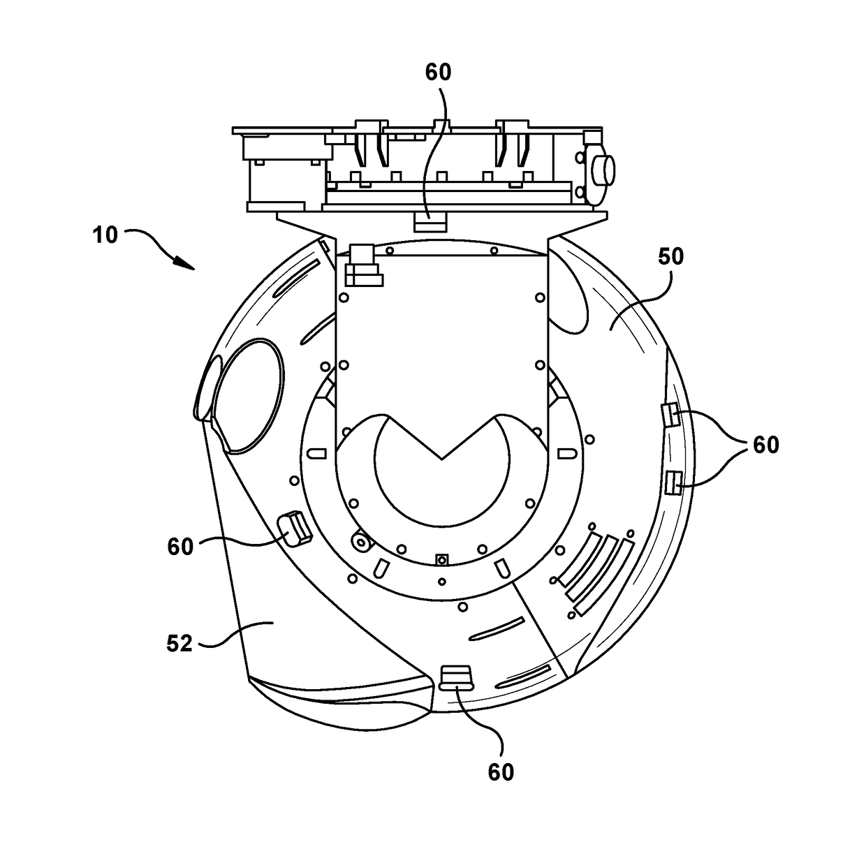
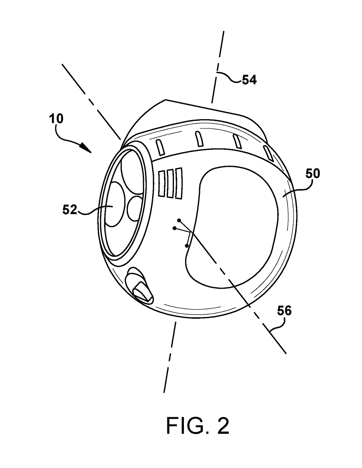
[0048]The present invention provides a shock-resisting device including an actuatable snubber for restraining an inner payload, such as an inner gimbal, relative to an outer member, such as an outer shell. For example, the exemplary device may be utilized for restraining an inner optics payload relative to an external gimbal or frame of a vehicle, such as an aerial vehicle. The shock-resisting device, and particularly the actuatable snubber, is rapidly deployable and protects the payload from shock damage, such as by providing a stiff attachment between the inner payload and the outer member. The shock-resisting device is configured to serve as a failsafe, deploying in the event of power loss to any of the vehicle as a whole, the inner payload, the shock-resisting device, the snubber of the shock-resisting device, or to a particular component of the actuatable snubber.

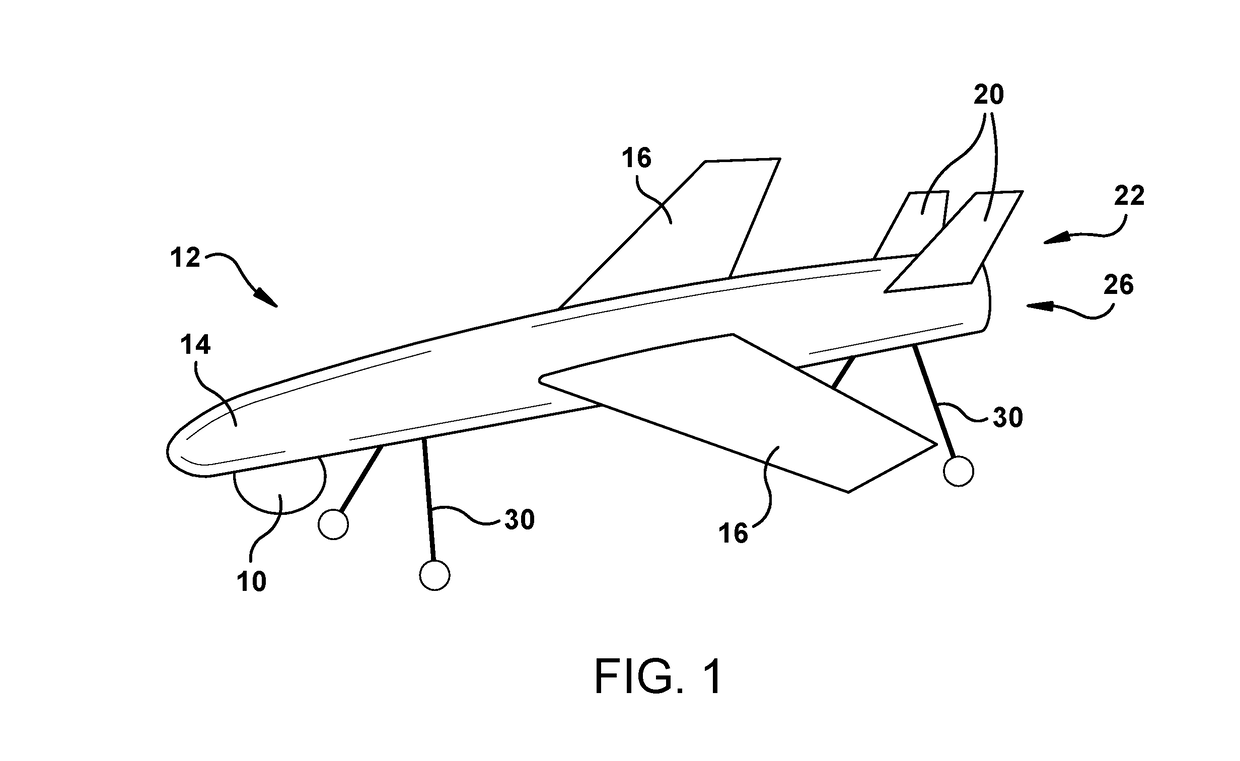
[0049]FIG. 1 illustrates an exemplary shock-resisting device 10 that is part of an unmanned aerial vehicle (UAV) 12....


PUM


Abstract

A shock-resisting device includes a snubber that may be selectively moved from a retracted position to an engaged position to selectively create a stiff attachment between a vibration-isolated gimbal of the device, and an outer shell of the device. The gimbal is movable relative to the outer shell. The snubber includes a retainer maintaining the snubber in the retracted position, wherein the snubber is configured to move from the retracted position to the engaged position in response to loss of power to the retainer.

Description

FIELD OF THE INVENTION[0001]The invention relates generally to a shock-resisting device and method, and more particularly to a rapidly deployable shock-resisting device for restraining an inner payload relative to an outer shell and respective method.DESCRIPTION OF THE RELATED ART[0002]Force isolation is advantageous particularly to isolate a complex, sensitive, critical, and / or expensive component from vibration, shock, or impact. In such an arrangement there may be damping devices between parts, with the vibration-isolated part able to move to some extent relative to the other part. One problem is that severe shocks to such systems may cause undesirable movement or forces on the isolated parts. It would be desirable for improvements in such devices such as to create a stiff attachment between the vibration-isolated part and another part, and in methods of using such devices.SUMMARY OF THE INVENTION[0003]The present disclosure provides an exemplary shock-resisting device including ...

Claims


Application Information

Patent Timeline
IPC IPC(8): B64D47/08F16F15/067B64C39/02F16M13/02
CPCB64D47/08F16M13/022B64C2201/127B64C39/024F16F15/067F16F15/02G03B15/006G03B17/561G01C19/26B64U2101/30
Inventor LAVINE, JASONGRAUE, BRIAN M.MILLER, BRETT A.
Owner RAYTHEON CO
Why Eureka
Try Eureka