Pivoting strain relief bar for data patch panels

a technology of strain relief bar and data patch panel, which is applied in the direction of coupling device details, cable junctions, coupling device connections, etc., can solve the problems of cable performance degradation, many problems, and repair or replace the termination or the entire cabl

Inactive Publication Date: 2009-02-12
PANDUIT
View PDF17 Cites 81 Cited by
  • Summary
  • Abstract
  • Description
  • Claims
  • Application Information

AI Technical Summary

Benefits of technology

[0009]A pivoting strain relief bar assembly that is comprised of a patch panel rotatably coupled to a strain relief bar, where the patch panel and strain relief bar are also coupled to a conventional rack capable of supporting telecommunications or other electronic equipment. Cables that are to be terminated to the patch panel are secured to and supported by the strain relief bar. The strain relief bar is capable of locking in a substantially horizontal position and thus remains fixed while supporting a large number of network cables. The strain relief bar can also be unlocked and rotated, allowing a technician to access the patch panel without having to unnecessarily disconnect cables.

Problems solved by technology

If network cables are haphazardly connected directly into the patch panel, many problems would result.
Excessive loads, such as a downward shear force due to the unsupported weight of the loose network cable, can overstress the cable terminations, causing them to break or disengage from the jack, resulting in the need to repair or replace the termination or the entire cable.
Additionally, due to the heavy weight of the network cable, a small bending radius results where the cable bends downward under the influence of gravity near the point where the cable termination is connected to the jack.
This tight bending radius can result in physical damage to the cable itself, or can lead to cable performance degradation.
Finally, when a large number of cables are haphazardly routed to the patch panels, technicians would be unable to quickly disconnect and reconnect a group of cables and, thus, valuable time and money would be wasted whenever routine maintenance tasks were undertaken.
This process is cumbersome and time-consuming for the technician, who often must consult a diagram to ensure that the correct cables are inserted into the correct jacks.
However, the '665 patent suffers from several drawbacks.
This gradual downward rotation could block access to adjacent patch panels, resulting in the need for a technician to reposition multiple support bars in order to access a specific patch panel.
Additionally, this gradual rotation of support bars could result in the pinching of network cables between adjacent support bars.
Since the support bars are typically constructed from stamped sheet metal, the pinching of the cables could result in damage to the cables, requiring costly cable repair or replacement.

Method used


Image

  • Pivoting strain relief bar for data patch panels
  • Pivoting strain relief bar for data patch panels
  • Pivoting strain relief bar for data patch panels

Examples


Embodiment Construction

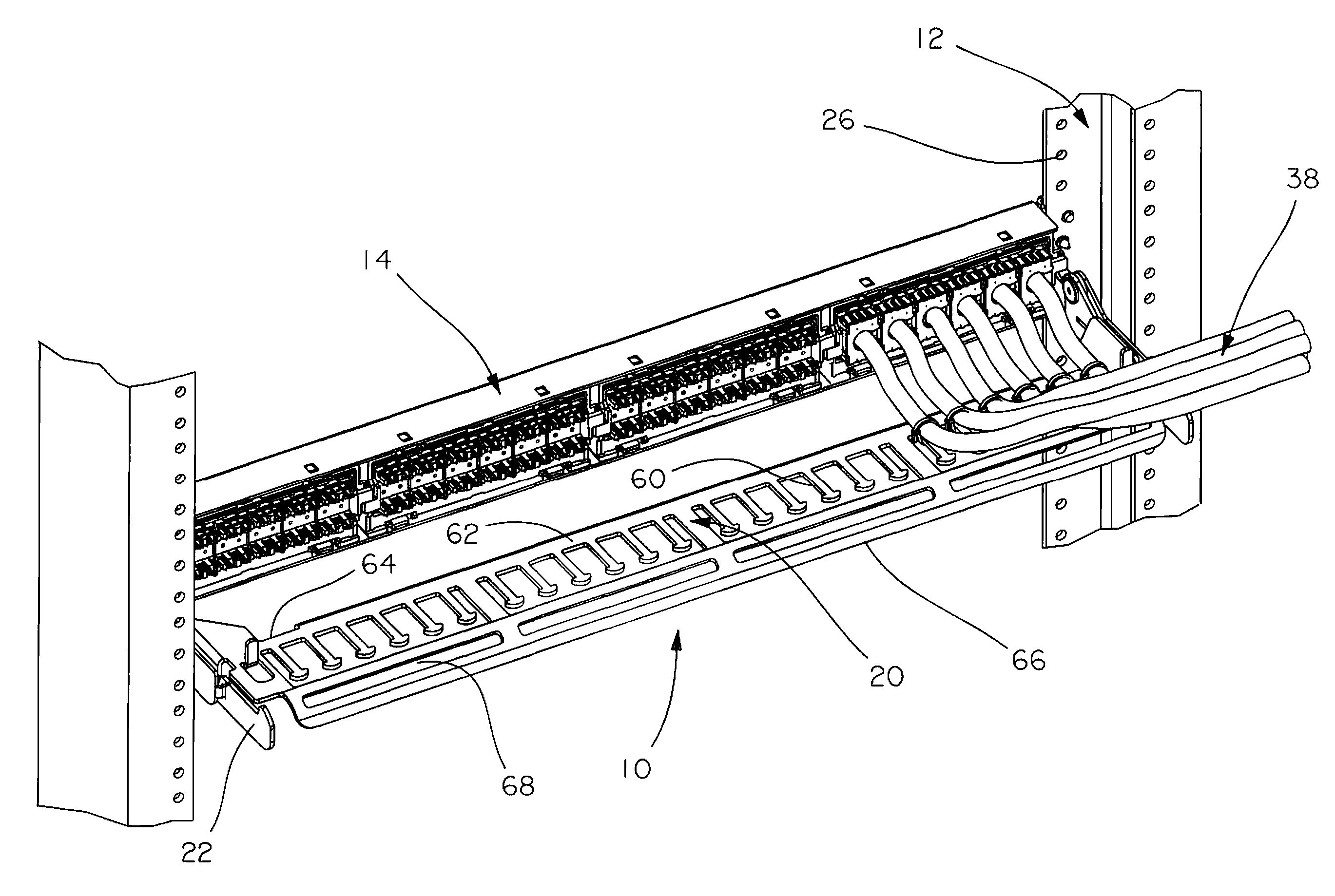
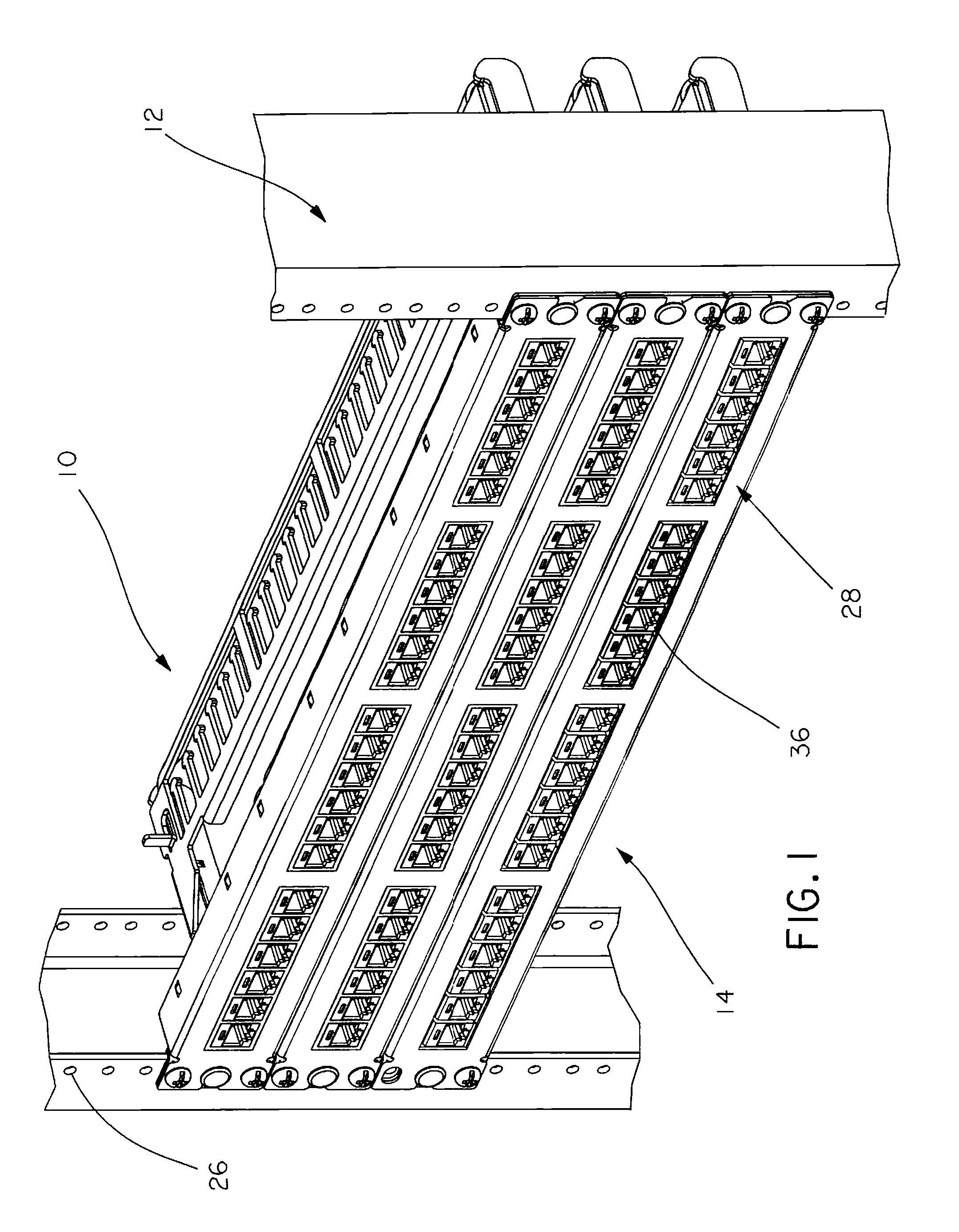
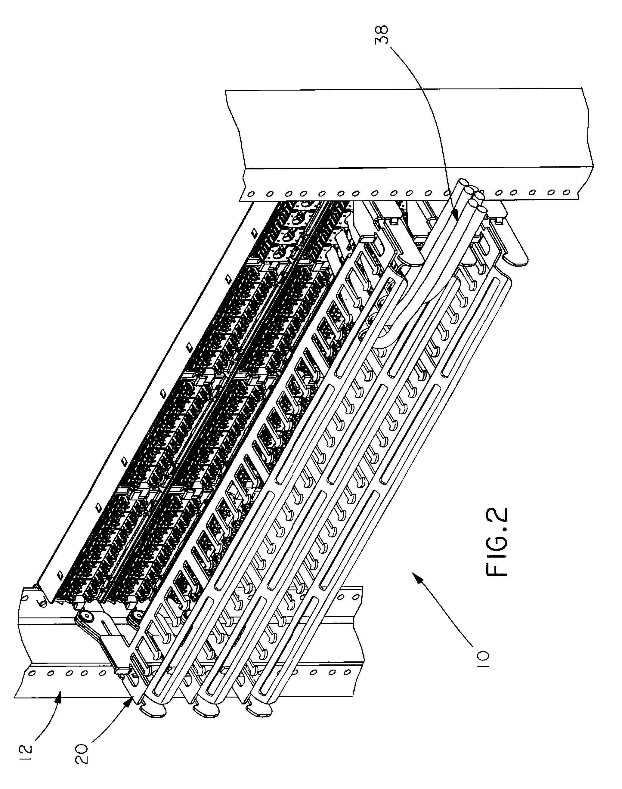
[0022]The illustrated embodiments of the Present Invention are directed to a pivoting strain relief bar assembly for organizing and supporting network data cables.

[0023]Referring now to the Figures, in which like elements are represented by the same reference numerals, a pivoting strain relief bar assembly for organizing and supporting network data cables is generally indicated in FIG. 1 by reference numeral 10. Pivoting strain relief bar assembly 10 preferably includes a support rack 12, a patch panel 14 coupled to the support rack 12, at least one side bracket 16 coupled to the support rack 12 and the patch panel 14, a bracket latch tab 18 integrally formed on at least one side bracket 16, a strain relief bar 20 rotatably coupled to at least one side bracket 16, and at least one finger tab 22 integrally formed with the strain relief bar 20 wherein the finger tab 22 includes a latch slot 24 adapted to receive the bracket latch tab 18 and thereby lock the strain relief bar 20 in a h...


PUM


Abstract

A pivoting strain relief bar assembly that is comprised of a patch panel rotatably coupled to a strain relief bar, where the patch panel and strain relief bar are also coupled to a conventional rack capable of supporting telecommunications or other electronic equipment. Cables that are to be terminated to the patch panel are secured to and supported by the strain relief bar. The strain relief bar is capable of locking in a substantially horizontal position and thus remains fixed while supporting a large number of network cables. The strain relief bar can also be unlocked and rotated, allowing a technician to access the patch panel without having to unnecessarily disconnect cables.

Description

FIELD OF THE PRESENT INVENTION[0001]The Present Invention is directed to a device used to organize and support network cables and, more particularly, to a strain relief bar rotatably coupled to a data patch panel.BACKGROUND OF THE PRESENT INVENTION[0002]Local area networks and telecommunications connections often use data patch panels to enable inter or cross-connection between telecommunications equipment. Patch panels typically comprise a frame member having a plurality of connector locations wherein any of a plurality of jacks may be mounted. The jacks allow for rapid connection and disconnection of network cable between jacks in the same patch panel or between jacks located on different patch panels.[0003]If network cables are haphazardly connected directly into the patch panel, many problems would result. Typically, the terminations at the terminal end of network cables are designed only to maintain a mating relationship with the jack. Excessive loads, such as a downward shear ...

Claims


Application Information

Patent Timeline
Patent Type & Authority Applications(United States)
IPC IPC(8): H01R4/00
CPCH01R9/2416H01R13/518H01R24/64H04Q1/021H04Q1/13H04Q1/064
Inventor FRANSEN, ROBERT E.DONNELL, MARK J.HERBST, PAUL M.
Owner PANDUIT
Why Eureka
Try Eureka