Neck for a robotic welding torch

a welding torch and robotic technology, applied in welding apparatus, shielding gas supply/evacuation devices, manufacturing tools, etc., can solve the problems of inability to make any number of mounting arms, parts are put through imprecise operations, and finished neck parts are vulnerable to inconsistencies in length, bend location, overall dimensions, etc., to achieve accurate and successful welding operations

Active Publication Date: 2009-02-12
ILLINOIS TOOL WORKS INC
View PDF5 Cites 24 Cited by
  • Summary
  • Abstract
  • Description
  • Claims
  • Application Information

AI Technical Summary

Benefits of technology

[0009]The present invention provides a neck for a robotic welding torch that provides for precise and repeated location of the tool center point (TCP) of the welding torch. The welding torch is thereby capable of repeatedly performing accurate and successful welding operations.

Problems solved by technology

Further, it is not difficult to make any number of mounting arms to the exact (or nearly exact) same dimensions.
On the other hand, the neck portion is conventionally made of brass, copper, and / or aluminum tubular parts that are precision machined, but these parts are put through imprecise operations such as brazing and bending during assembly.
This makes finished neck portions vulnerable to inconsistencies in length, bend location, and overall dimensions.
Additionally, the lack of precision in the bending and / or brazing operations makes repeatability difficult in the manufacturing of the neck portions.
Therefore, it is difficult to manufacture even two neck portions that have exactly the same dimensions.
Further, due to the relatively small diameter and inherent softness of the materials from which the neck portion is made, the neck portion is not truly rigid.
All of these factors combine to have a detrimental effect on both locating and maintaining the TCP.
This checking and manipulating of the neck portion's TCP is time consuming and does not always result in a neck portion having an acceptable TCP.
Also, it is common during a welding process that movement of the robot will cause the neck portion to accidentally hit a fixed object such as the workpiece being welded or a clamp / fixture that is holding the workpiece in place.

Method used


Image

  • Neck for a robotic welding torch
  • Neck for a robotic welding torch
  • Neck for a robotic welding torch

Examples


Embodiment Construction

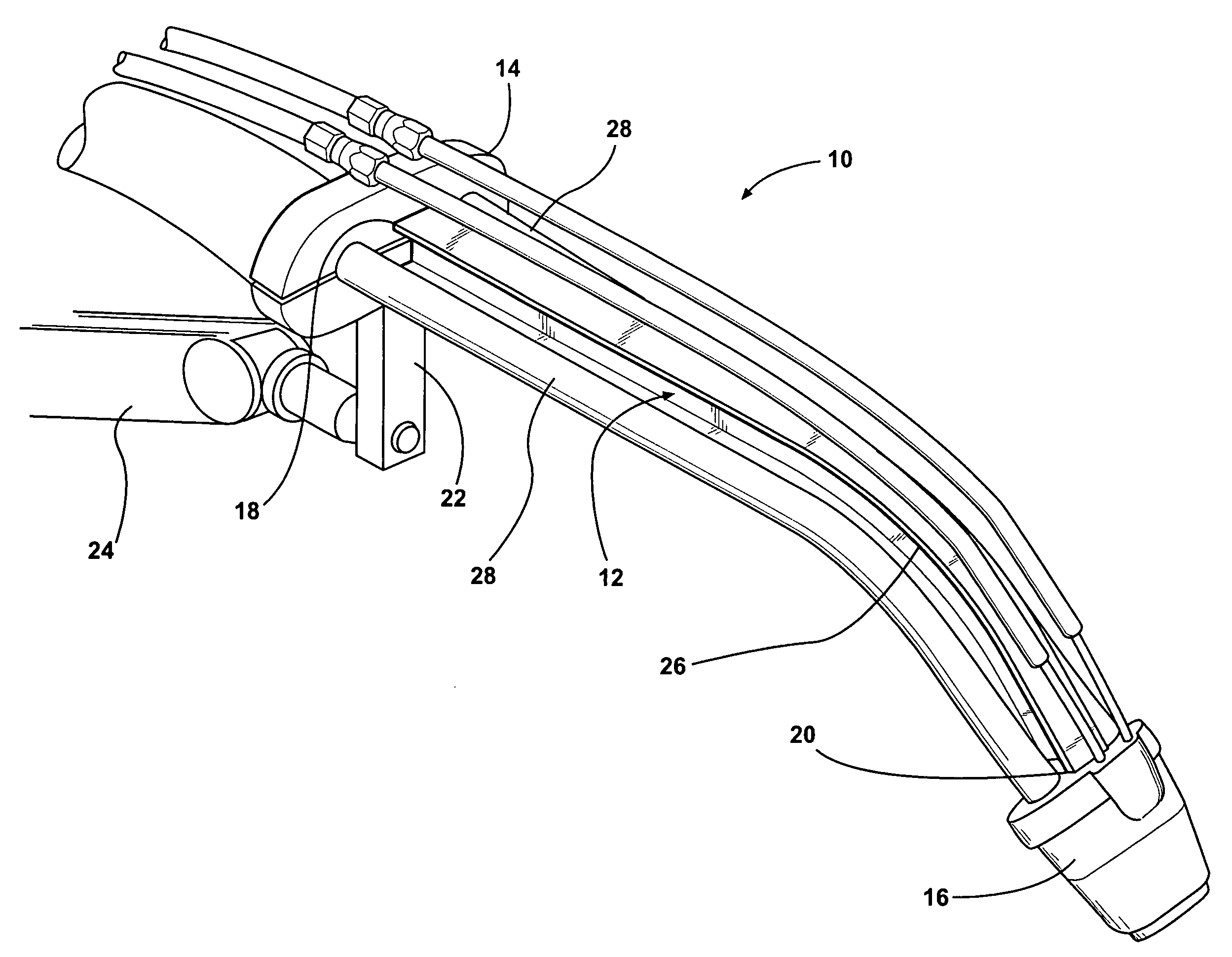
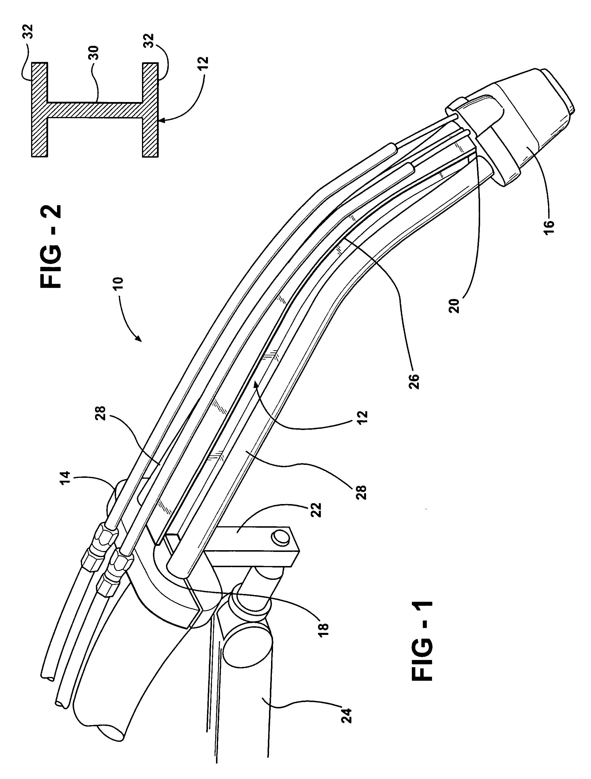
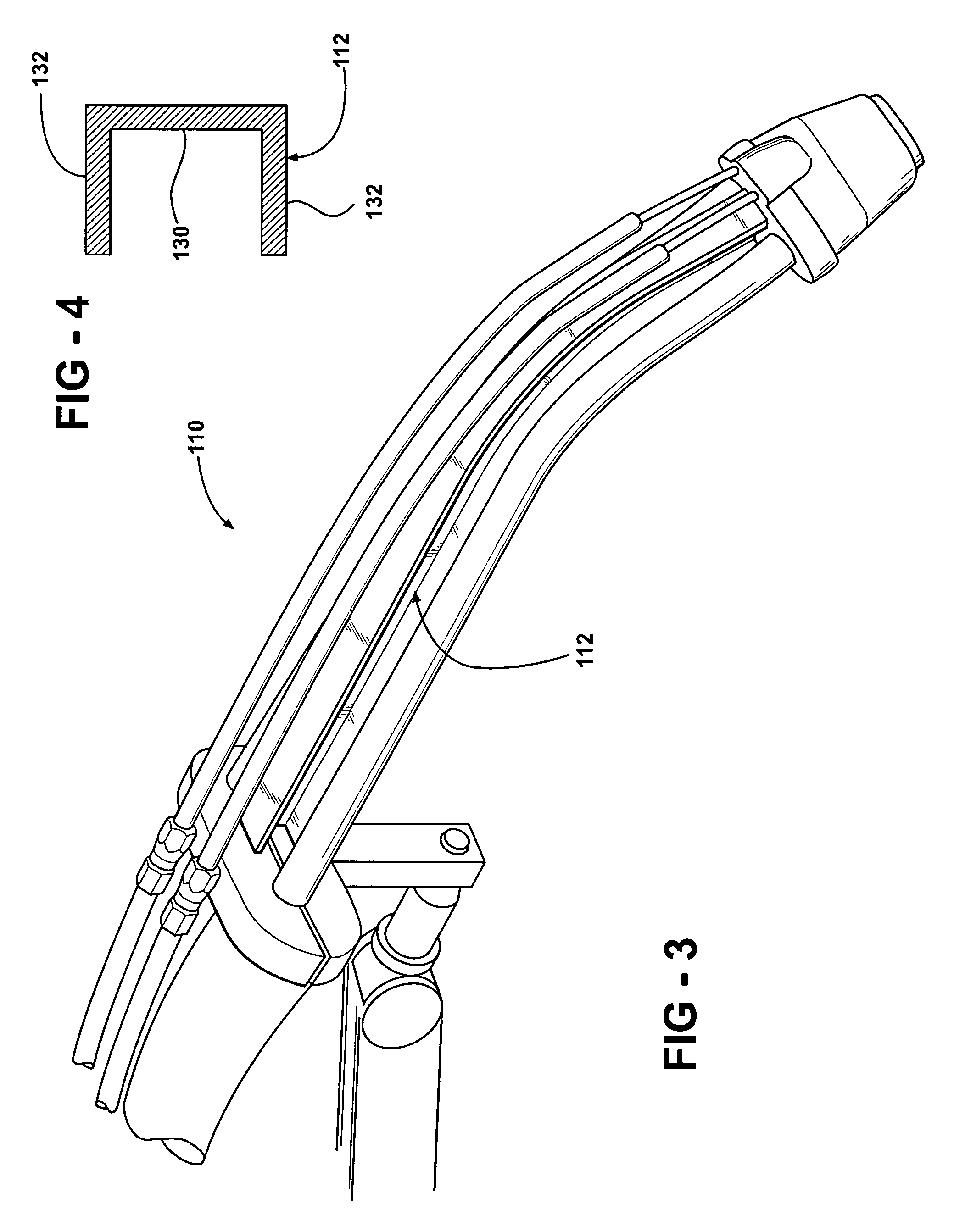
[0024]Referring now to the drawings in detail, numeral 10 generally indicates a welding torch in accordance with the invention. The welding torch 10 includes a neck 12 that has a precision machined structure that provides for precise and repeated location of a tool center point (TCP) of the welding torch. The precision machining of the neck results in the neck having more accurate dimensions and geometry in comparison to conventional necks. The neck 12 is also structurally stronger than conventional tubular necks, offering more support for a welding tip and nozzle during a welding operation. The neck 12 is also less likely to bend out of alignment due to inadvertent contact with other objects such as workpieces, fixtures, or similar.

[0025]With reference to FIGS. 1 and 2, the welding torch 10 includes a rear portion 14 such as a main housing or body. The rear portion 14 may connect the welding torch 10 to a flexible cable such as a unicable or similar welding cable assembly that carr...


PUM

PropertyMeasurementUnit
shapeaaaaaaaaaa
lengthaaaaaaaaaa
poweraaaaaaaaaa

Abstract

A neck for a welding torch includes a rigid, non-tubular, elongated member having opposite first and second ends. The first end is connectable to a rear portion of the welding torch. The second end is connectable to a welding tip portion of the welding torch. The member locates and holds the welding tip portion in a precisely given location, and does not communicate welding power, welding wire, shielding gas, or cooling water between the first and second ends.

Description

CROSS REFERENCE TO RELATED APPLICATION[0001]This application claims the priority of U.S. Provisional Application No. 60 / 964,263 filed Aug. 10, 2007.TECHNICAL FIELD[0002]This invention relates to welding torches mountable on a robot, and more particularly to a neck of a welding torch.BACKGROUND OF THE INVENTION[0003]It is known in the art relating to welding torches that welding torches generally include a flexible cable portion that delivers power, shielding gas, welding electrode, and sometimes cooling water to a tubular neck portion, which may be referred to as a gooseneck or swanneck. The neck portion delivers the power, shielding gas, welding electrode, and cooling water (if present) to a tip portion that is secured to an end of the neck portion. The tip portion may include a welding tip and a nozzle. Typically, a mounting arm that mounts the welding torch to a welding robot is attached to the welding torch at a point between the cable portion and the neck portion.[0004]Accuracy...

Claims


Application Information

Patent Timeline
Patent Type & Authority Applications(United States)
IPC IPC(8): B23K9/10
CPCB23K9/1735B23K9/325B23K9/295
Inventor CENTNER, ROBERT J.
Owner ILLINOIS TOOL WORKS INC
Why Eureka
Try Eureka