
Extractor of dry grains from a silo bag

Inactive Publication Date: 2009-02-12
CARLOS MAINERO & CIA SAICFI
View PDF6 Cites 17 Cited by
  • Summary
  • Abstract
  • Description
  • Claims
  • Application Information

AI Technical Summary

Benefits of technology

The technical effect of this patent is that it provides a solution for issues related to storing dried grains by introducing an improved method. This includes developing ways to cut and empty the bags used for packaging the grains more efficiently.

Problems solved by technology

The technical problem addressed by this patent is how to efficiently use special bags (known as silo-bags) during crop production and delivery without requiring expensive equipment or complicated procedures. These bags provide protection for the grain while avoiding damage during transfers between different locations, but current methods of cutting and emptying them can be difficult and imprecise. This patent seeks to solve these issues and improve the overall efficiency of the process.

Method used


Image

  • Extractor of dry grains from a silo bag
  • Extractor of dry grains from a silo bag
  • Extractor of dry grains from a silo bag

Examples


Embodiment Construction

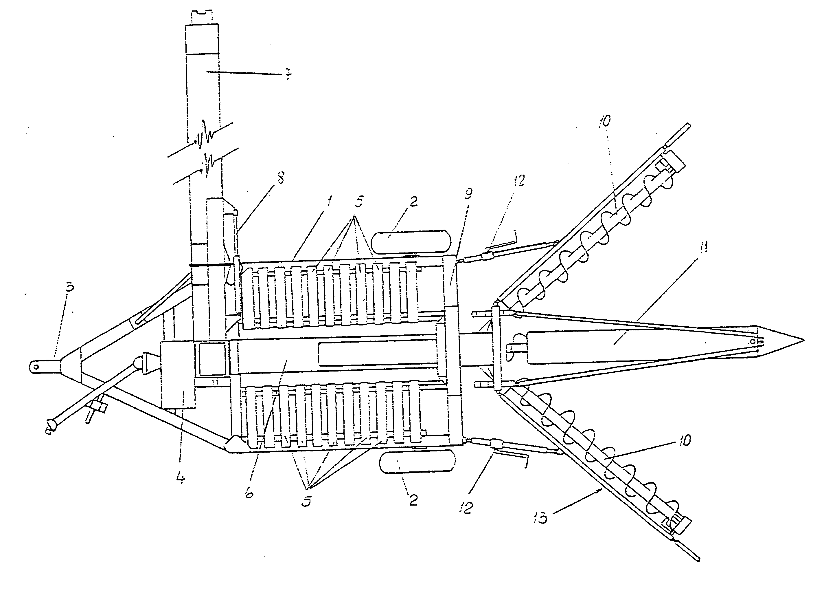
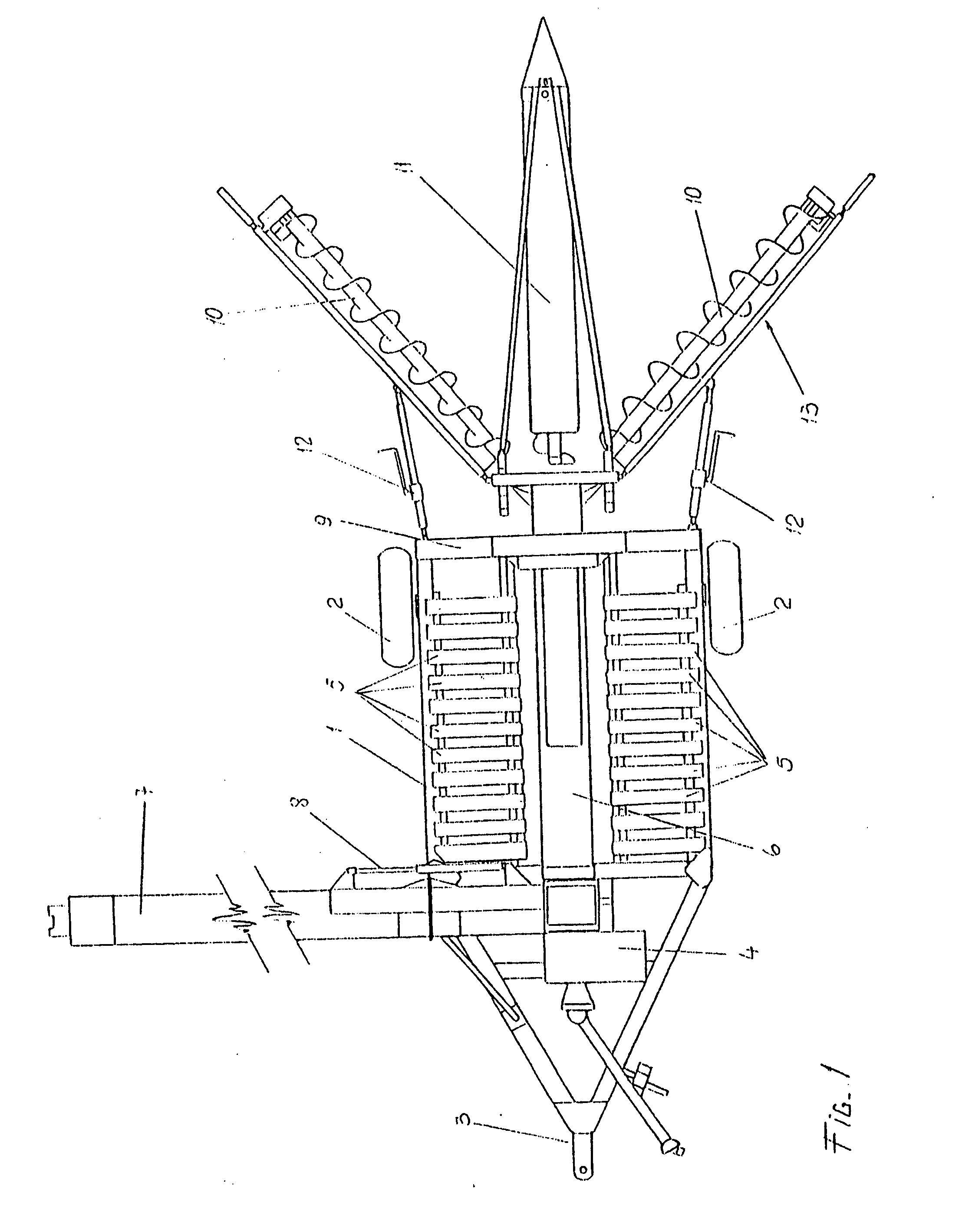
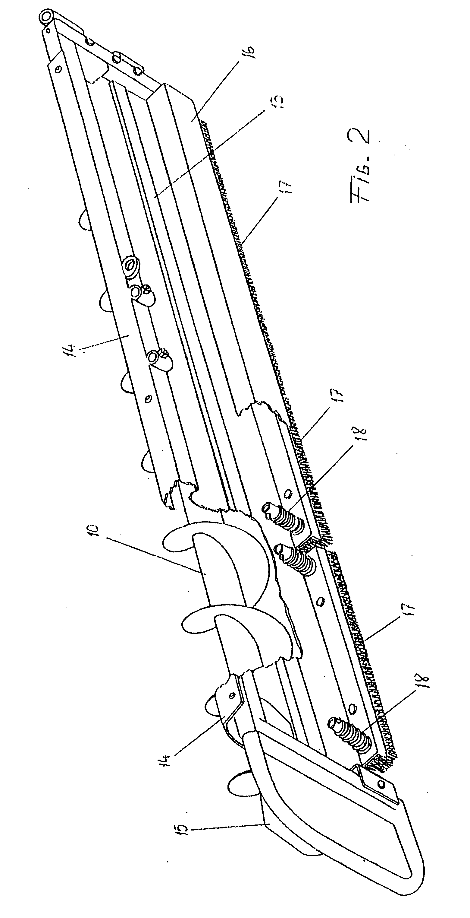
[0014]In order to make this invention understandable so as to be carried out easily, an accurate description of a preferable way of carrying it out it is given in the paragraphs hereinafter mentioned, by making reference to the illustrative drawings attached hereto. The description is given purely as a demonstrative example, but not limited, of the invention. Its components may be selected from several similar devices, but it shall be dully follow the principals of the invention set forth in this document.

[0015]In the drawings described previously, the references show same parts or similar parts, being number 1, a chassis; number 2, a wheel; number 3, a spear; and number 4, an hydraulic pump.

[0016]With number 5 is established a panel; with number 6, an unloading pipe; with number 7, an unloading tube; and with number 8, a hydraulic cylinder.

[0017]Number 9 indicates a vertical frame; number 10, a lateral worm; number 11, a central worm; and number 12, a handhole.

[0018]Number 13 refer...


PUM


Abstract

The chassis provides a hollow vertical frame connected to a floating extraction unit and two platforms which are formed by several panels transversally aligned to each side of an unloading pipe, which feeds a folding unloading tube. Between the extraction unit and the vertical frame, it is provided a spring unit and a hydraulic cylinder, both modifiers of the height. The extraction unit is formed by a central worm and two lateral worms, hydraulically adjustable in height, and two sweeping units. Each sweeping unit is connected to a plate over which there is supply for deviating the grain. Under it, there are settled the pipes of the hydraulic circuit, a scrapper of the inner wall of the silo-bag connected to the front edge of such plate, shaped as a flexible laminar body. Furthermore, it has an box bearing at least one floating brush, which bristles exceed the lower edge of the plate and they are in permanent contact with the ground of the silo-bag. The lateral worms provide a varying handhole of the opening and closing angles.

Description


Claims


Application Information

Patent Timeline
Owner CARLOS MAINERO & CIA SAICFI
Learn More