Compact Drain Assembly for Sinks and the Like

Inactive Publication Date: 2009-02-19
ELLECI
7 Cites 0 Cited by

AI-Extracted Technical Summary

Problems solved by technology

Another drawback further consists in that it is necessary to provi...

Benefits of technology

[0007]The aim of the invention is to eliminate the drawbacks mentioned above by providing a compact drain assembly for sinks and the like which allows to reduce d...

Abstract

A compact drain assembly for sinks and the like, comprising at least one drain duct which can be coupled hermetically at a drain hole which is provided at least at the lateral surface of a sink and has at least one portion which is at the same level as, or lower than, the bottom of the sink. An element for closing the drain is further provided which affects the drain duct.

Application Domain

Technology Topic

EngineeringDrain tube

Image

  • Compact Drain Assembly for Sinks and the Like
  • Compact Drain Assembly for Sinks and the Like
  • Compact Drain Assembly for Sinks and the Like

Examples

  • Experimental program(1)

Example

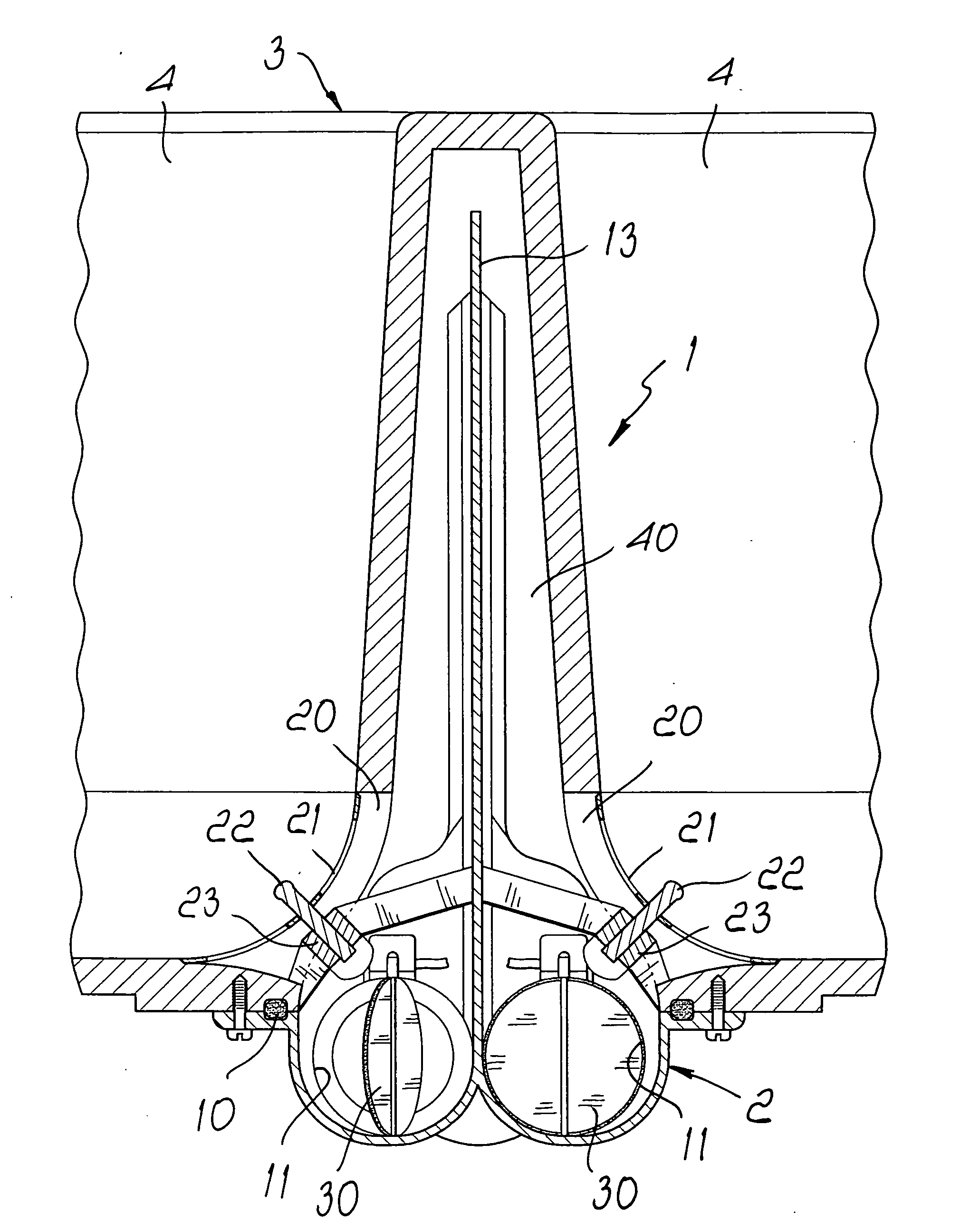
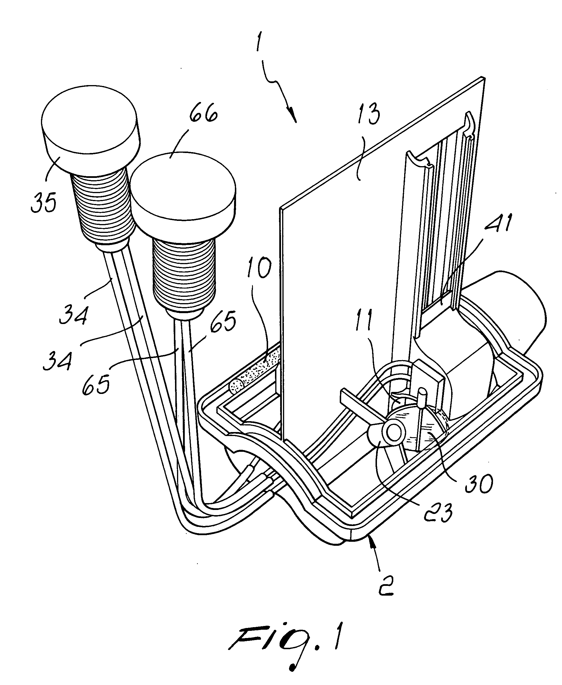
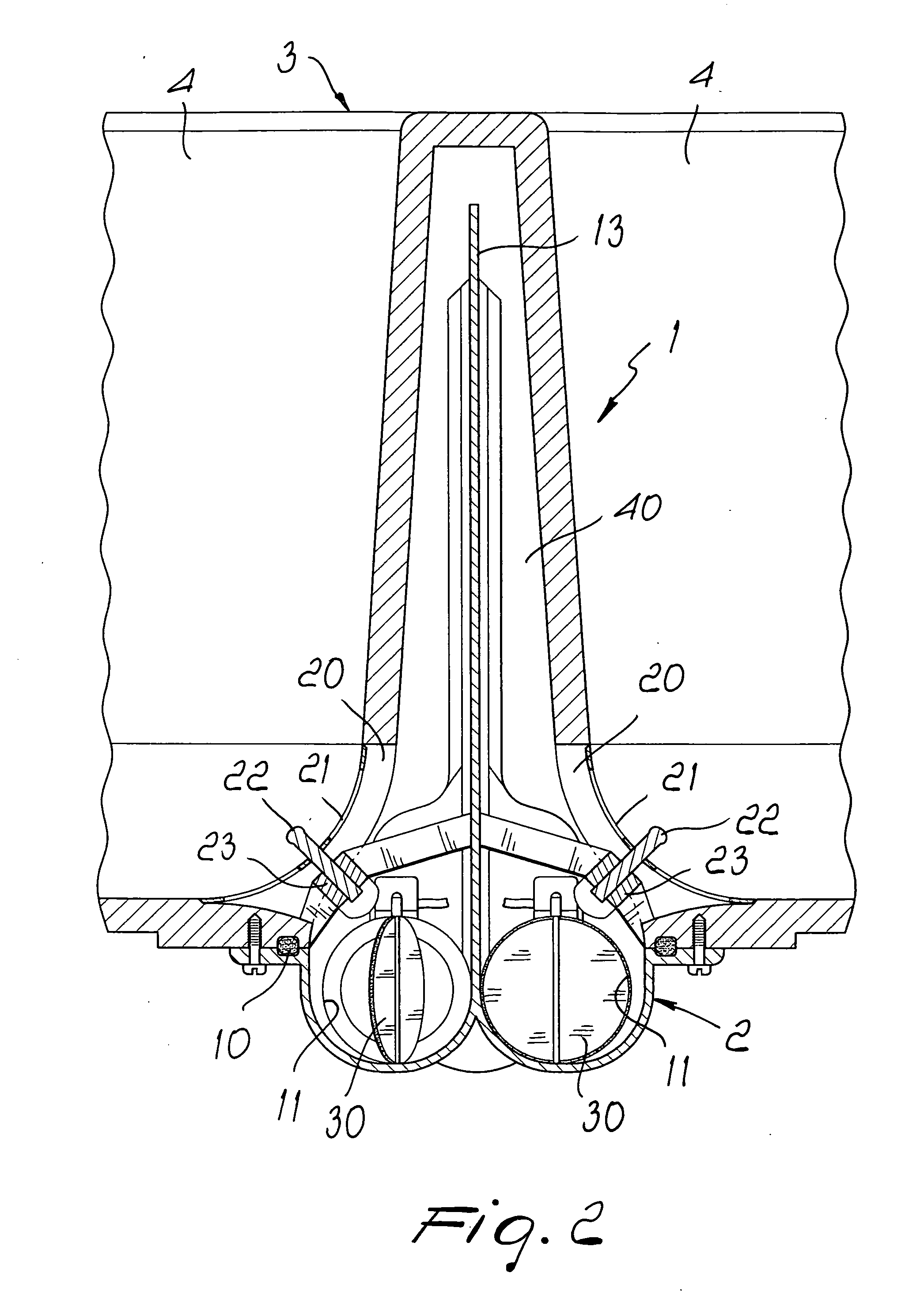
[0020]With reference to the figures, the compact drain assembly for sinks and the like, generally designated by the reference numeral 1, comprises a bowl element 2, which can be applied hermetically to a sink and the like, generally designated by the reference numeral 3, preferably at the region between the two bowls 4 of a sink or, in the case of a single-bowl sink, on the side of a bowl 4.
[0021]The bowl element 2 is provided with a sealing gasket 10, which acts on the outer surface of the sink 3 so as to optimize the hermetic coupling.
[0022]The sink 3 is connected to a drain duct 11, which is provided so that it has a drain duct 11 for each bowl 4.
[0023]In the case of two bowls, as shown schematically in FIG. 1, there are two ducts 11, which are mutually separated by a partition wall 13 which substantially divides the region arranged between the two bowls.
[0024]A peculiar feature of the invention consists in that each drain duct 11 is connected to a respective bowl 4 by means of a drain hole 20, which is arranged laterally in order to affect the lateral surface of the sink and also a portion which is flush with the bottom of the sink, so as to allow complete discharge of the water, allowed by the fact that the bottom of the sink is provided so that it slopes toward the drain hole.
[0025]The drain hole 20 is closed by a grille 21, which acts only as a barrier but does not provide a seal and is provided with a grip pin 22, which can be accommodated in a spoked element 23 so as to retain the grille 21 in position.
[0026]A drain closure element is provided at each drain duct 11 and in practice replaces the conventional closure plug of the bowl, which in the specific case is closed by means of a flow control element which can be of any type and advantageously can be actuated remotely.
[0027]In the specific example, which illustrates one of the possible embodiments, there is a flow control element with a flap 30 which rotates about its own axis and has a pivot 31 which protrudes radially from the flap-like flow control element 30 and is connected to a gear 32, which meshes for example with a rack 33 which can slide by way of the action of a cable 34 which can be actuated from a control knob 35 which can be arranged above the sink.
[0028]In this manner, by turning the flap-like flow control element 30, the drain duct is opened and closed, controlling the outflow of the liquid from the bowl.
[0029]With the described arrangement it is therefore possible to reduce drastically the space occupation below the sink, since it is not necessary to provide a connection to the drain pipe, but the drain duct lies substantially horizontally at a level which is slightly lower than the bottom of the sink, so that the space below the bowl is left completely free.
[0030]Moreover the solution used allows to provide an overflow which can be obtained without having to produce another hole in the bowl.
[0031]In the specific case, the overflow function is achieved by means of a chamber 40 which is provided laterally with respect to the bowl and is delimited by a level control partition 41, which can slide so as to vary its useful height, which determines the level of overflow of the water, said overflow occurring downstream of the flow control element 30, with reference to the direction of outflow of the water.
[0032]The level partitions 41 can be adjusted in height so that each user can freely define the overflow level simply by varying the height of the partition 41, which can slide in hermetic guides 42 provided in the dividing wall 13 or in any case laterally adjacent to the sink, so as to define an overflow region, beyond which the water passes directly to the drain.
[0033]In order to position the level control partition it is possible to use different actuation means; according to a possible embodiment, which must not be construed as limiting, it is possible to provide a linear set of teeth 60 on the partition 41, such set being engaged by an actuation gear 61 arranged on a shaft 62 provided with a pinion 63 which meshes with a hook-like detent system 64 actuated by a cable 65, which can be operated by means of a level knob 66 which can be accessed above the sink.
[0034]The rotation of the gear 61 changes the vertical position of the partitions and consequently changes the overflow level according to the requirements of the user.
[0035]From what has been described above it is therefore evident that the invention achieves the intended aim and objects, and in particular the fact is stressed that a drain assembly for sinks and the like is provided which allows first of all to reduce drastically the space occupation under the sink and further allows to obtain the overflow safety level without having to resort to the additional traditional provision of a hole in the bowl of the sink.
[0036]Another important aspect further consists in that it is possible to adjust the overflow level at will.
[0037]The invention thus conceived is susceptible of numerous modifications and variations, all of which are within the scope of the appended claims.
[0038]All the details may further be replaced with other technically equivalent elements.
[0039]In practice, the materials used, as well as the contingent shapes and dimensions, may be any according to requirements.
[0040]The disclosures in Italian Patent Application No. MI2006A000527 from which this application claims priority are incorporated herein by reference.

PUM

no PUM

Description & Claims & Application Information

We can also present the details of the Description, Claims and Application information to help users get a comprehensive understanding of the technical details of the patent, such as background art, summary of invention, brief description of drawings, description of embodiments, and other original content. On the other hand, users can also determine the specific scope of protection of the technology through the list of claims; as well as understand the changes in the life cycle of the technology with the presentation of the patent timeline. Login to view more.

Similar technology patents

Process for determining a time interval

InactiveUS20070085726A1Increase precision and interference resistanceReduced space requirementUsing electrical meansConverting sensor outputEngineeringMeasurement precision
Owner:ASM AUTOMATION SENSORIK MESSTECHN GMBH

Engine intake control device

Owner:MITSUBISHI ELECTRIC CORP

Classification and recommendation of technical efficacy words

  • Reduced space requirement
  • Eliminate drawback

Anti-drawback medical valve

InactiveUS7014169B2Eliminate drawbackEnlarge volume of interiorValve arrangementsSurgeryMechanical engineeringMedical treatment
Owner:NP MEDICAL

MRI compatible programmable valve pump

ActiveUS20100021311A1Eliminate drawbackContracting/expanding measuring chambersFlexible member pumpsControl electronicsDrug delivery
Owner:FLO(ABC) LLC

Mechanical roller tappet for an internal combustion engine

InactiveUS20100012065A1High shape stabilityEliminate drawbackValve drivesMachines/enginesEngineeringCam
Owner:SCHAEFFLER TECH AG & CO KG
Why Eureka
Try Eureka