
Outsole structure for a shoe, method for assembling outsole to an upper, and shoe obtained by said method

Inactive Publication Date: 2009-02-19
BERNARDESCHI LUIGI
View PDF11 Cites 12 Cited by
  • Summary
  • Abstract
  • Description
  • Claims
  • Application Information

AI Technical Summary

Benefits of technology

[0005]The object of the present invention is to overcome the disadvantages mentioned above by providing a new outsole structure and a new method of assembling the same to the upper which should allow obtaining shoes with side protrusions along the perimeter of the sole, substantially of the type mentioned above, with a considerably improved aesthetic result, with elementary and low cost manufacturing methods, further improving the comfort of the shoe and the durability requirements thereof.

Problems solved by technology

However, in this case, an external reinforcing seam connecting the outsole to the upper must necessarily be distributed on the upper leather, which is unavoidably superimposed externally to the rubber, close to the relevant protrusions.
This causes a loss in the very aesthetic value of the product, which is made even more serious by the leather sharp cut edge, which remains visible on the outside.
The handmade assembly between outsole and upper, moreover, can be difficult due to the need of maintaining an accurate superimposition of the leather during the stitching.
Due to these disadvantages, sometimes the external protrusions are obtained with separate rubber portions applied subsequently, which of course considerably increases manufacturing times and costs.
The superimposition may also be avoided, using an internal support element (a so-called “midsole”); similarly, this is a manufacturing difficulty which moreover decreases the comfort of the shoe.

Method used


Image

  • Outsole structure for a shoe, method for assembling outsole to an upper, and shoe obtained by said method
  • Outsole structure for a shoe, method for assembling outsole to an upper, and shoe obtained by said method
  • Outsole structure for a shoe, method for assembling outsole to an upper, and shoe obtained by said method

Examples


Embodiment Construction

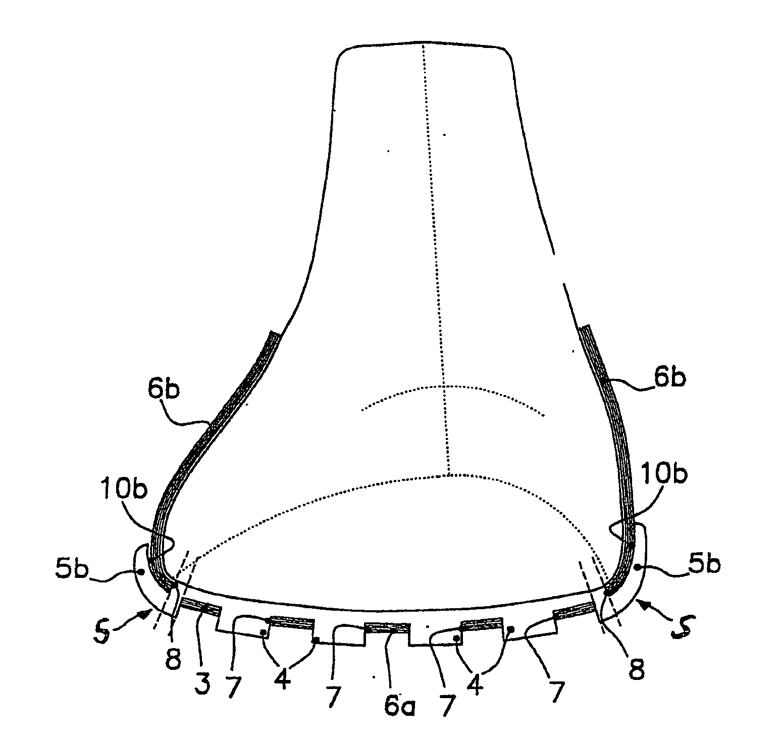
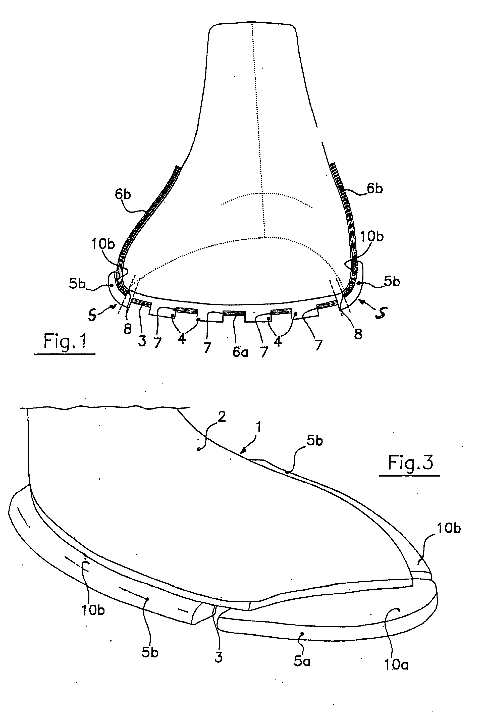
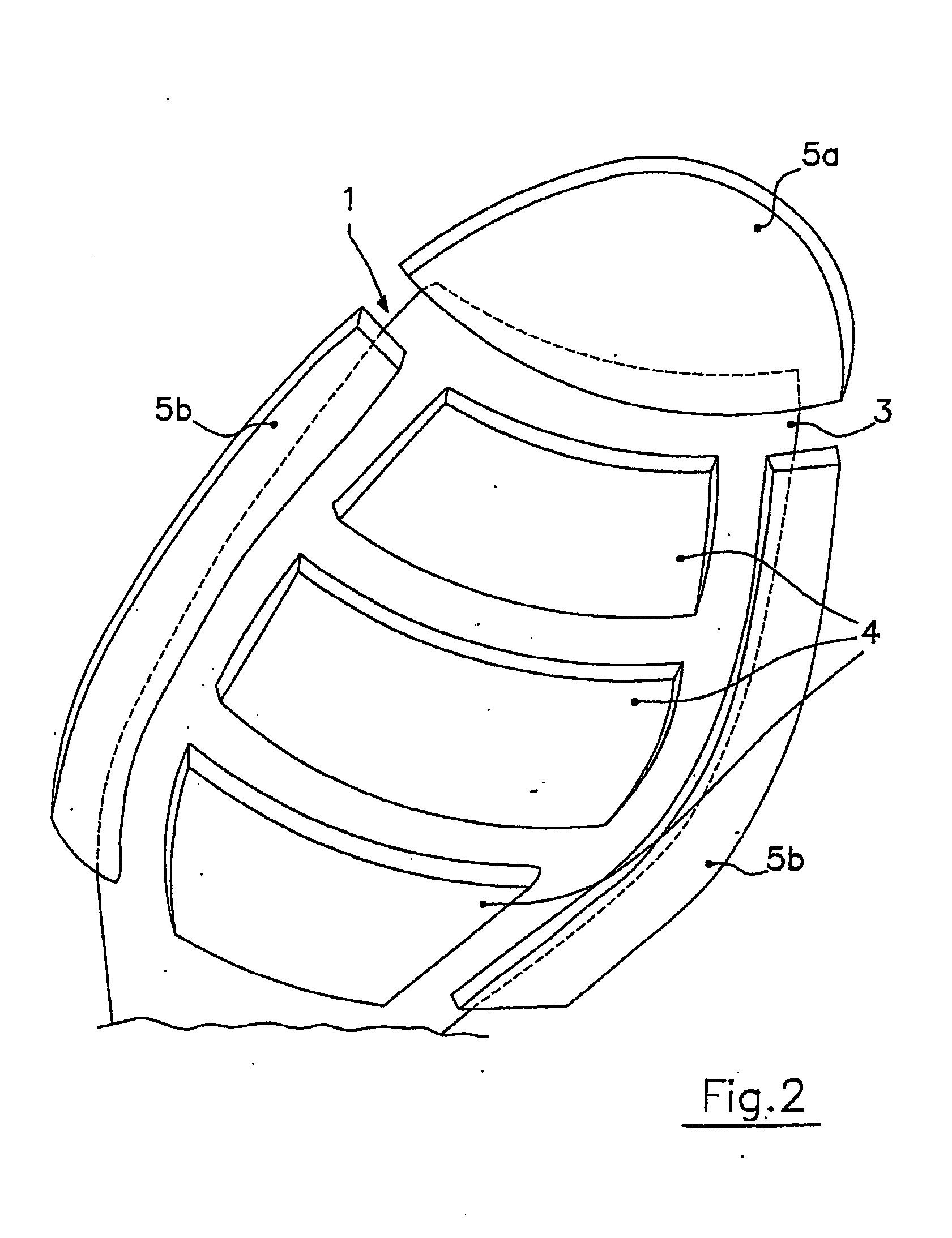
[0013]With reference to FIGS. 1 to 4, an outsole for a shoe according to the invention comprises a body 1 with substantially flat development, made of natural or synthetic rubber, shaped in accordance with the outline of the entire shoe sole or of just a portion thereof (for example the tip). In this second case, the shoe sole will be provided with two (or more) outsole semi-components physically separate from one another.

[0014]Body 1 therefore exhibits a top face 2, smooth in the schematic representation of FIG. 2 but which could actually be grooved or cut in various ways, intended for the foot's support with the interposition of an inter-sole and / or insole. Body 1 further exhibits a lower face 3 from which a distribution of protrusions projects, adapted for defining the actual sole tread. Among these protrusion, protrusions 4 can be noticed arranged in the inner zone of the lower face 3, that is, in a substantially central position, and peripheral protrusions 5, arranged along the...


PUM

PropertyMeasurementUnit
Thicknessaaaaaaaaaa
Structureaaaaaaaaaa
Areaaaaaaaaaaa

Abstract

A shoe outsole comprising a substantially flat body with a top face and a lower face exhibiting a distribution of tread protrusions. The protrusions include at least one peripheral protrusion extending beyond the peripheral edge and defining a top abutment surface displaced generally downward relative to the top face of the body. In a method of assembling the outsole to a shoe upper, for each peripheral protrusion, a cut is formed in the upper, developing in accordance with the profile of the area of superimposition between the peripheral protrusion and the body's lower face. The method provides for insertion of the at least one peripheral protrusion into the appropriate cut so as to enable passage of the protrusion below the upper as a superimposition reversal between the upper and the body.

Description

TECHNICAL FIELD OF THE INVENTION[0001]The present invention relates to the field of footwear and to the relevant manufacturing processes. In particular, it relates to a new outsole structure of natural or synthetic rubber and to the method of assembling it to the upper during the shoe manufacturing process. The invention relates also to the shoe obtained in this way.BACKGROUND OF THE INVENTION[0002]Various types of shoes are known wherein the upper, usually made of leather, has a base intended to be combined with a natural or synthetic rubber bottom or outsole, to obtain the shoe sole. In particular, the rubber outsole exhibits a number of outwards protrusions which, inserting into openings formed to this end in the base of the upper, become exposed, thus forming the actual sole tread. In practice, the outsole body is superimposed to the base, being kept on the inside of the shoe. The base, in the area without protrusions, remains exposed and visible between the protrusions, thus at...

Claims


Application Information

Patent Timeline
IPC IPC(8): A43B13/00A43C15/00A43D8/00A43B13/04A43B9/00A43B13/14A43B13/22A43B23/02
CPCA43B9/00A43B13/223A43B13/145
Inventor BERNARDESCHI, LUIGI
Owner BERNARDESCHI LUIGI
Learn More