Handlebar accessory clamp

Inactive Publication Date: 2009-02-19
ANDKJAR ERIC
View PDF21 Cites 14 Cited by
  • Summary
  • Abstract
  • Description
  • Claims
  • Application Information

AI Technical Summary

Benefits of technology

[0014]When used, the mounting surface is positioned toward the rider by rotating the mounting post to pan the mounting surface, by pivoting the yoke to tilt the mounting surface, and/or by rotating the mounting

Problems solved by technology

Such devices cannot be safely held by riders of handlebar-steered vehicles, such as motorcycles, ATVs, bicycles, and the like, while riding.
However, such devices have not enjoyed wide consumer acceptan

Method used


Image

  • Handlebar accessory clamp
  • Handlebar accessory clamp
  • Handlebar accessory clamp

Examples


Example

[0021]In the following description, terms such as horizontal, upright, vertical, above, below, beneath, and the like, are used solely for the purpose of clarity in illustrating the invention, and should not be taken as words of limitation. The drawings are for the purpose of illustrating the invention and are not intended to be to scale.

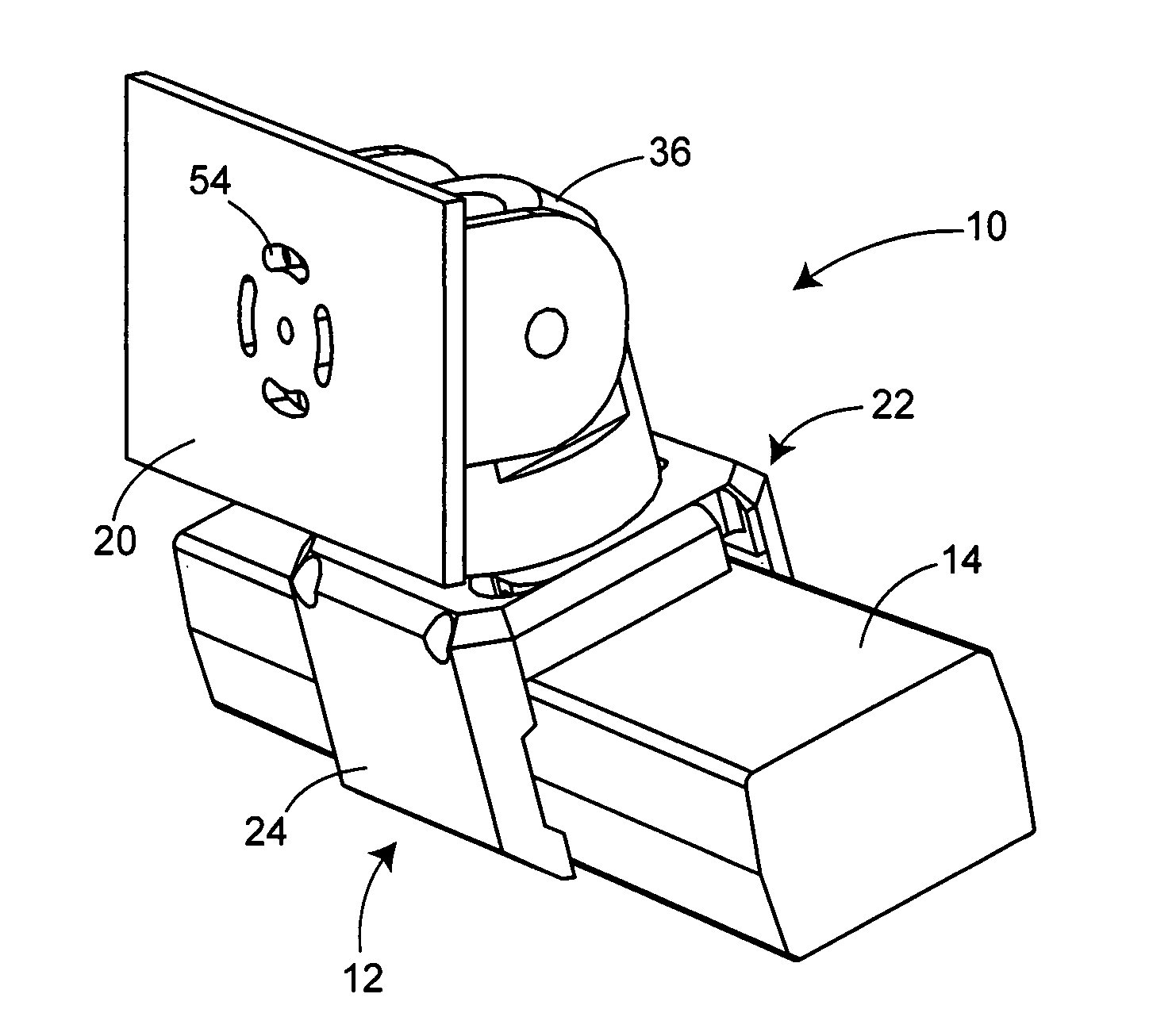
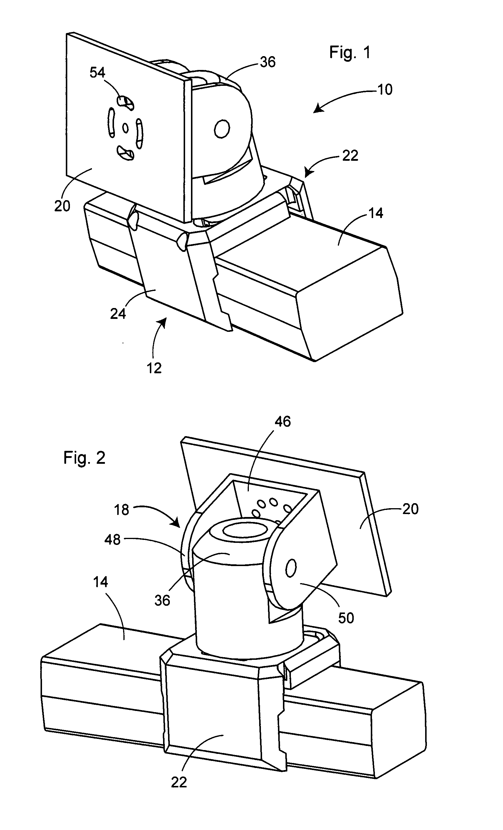
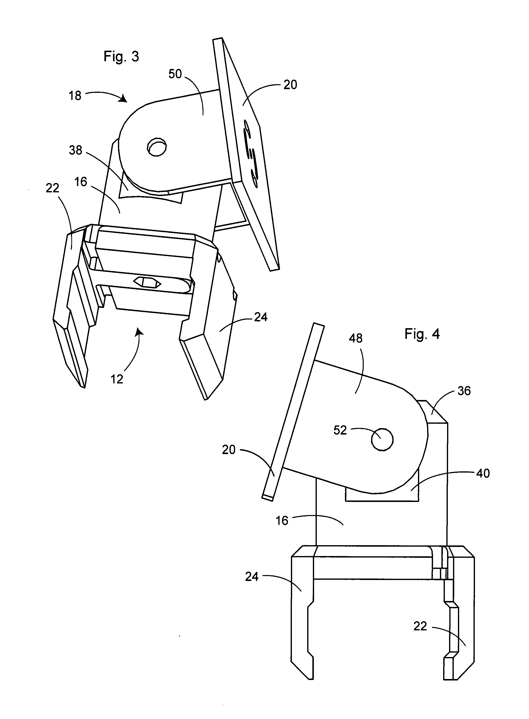
[0022]As illustrated in the drawings, a preferred embodiment of the mounting device, generally 10, is comprised of clamp, generally 12, releasibly attachable to a handlebar 14, mounting post 16 rotatably attached to the upper surface of clamp 14, mounting yoke, generally 18, pivotally attached to post 16, and accessory mounting plate 20 rotatably attached to yoke 18.

[0023]Clamp 12, best illustrated in FIG. 6, is comprised of front and back clamp sections 22 and 24, respectively. Clamp section 24 includes upper surface 26 for attachment of mounting post 16, while clamp section 22 includes first and second arms slidable into recesses in top plate 26 wi...


PUM


Abstract

A compact mounting device for releasibly securing a GPS receiver or other electronic accessory to a handlebar of a motorcycle or other handlebar-steered vehicle is described. The device includes a clamp releasibly attachable to a motorcycle handlebar; a cylindrical mounting post rotatably attached to the upper surface of the clamp; a mounting yoke pivotally attached to the mounting post; and a mounting plate to support a GPS receiver or other accessory rotatably attached to the yoke. The face of the accessory can be oriented toward the vehicle rider by rotating the post, tilting the yoke and/or rotating the mounting plate, so that the device is useable with a wide variety of handlebar orientations.

Description

BACKGROUND OF THE INVENTION[0001](1) Field of the Invention[0002]The present invention relates to a device for attaching an electronic accessory to a vehicle handlebar, and in particular to a compact device enabling three-way positioning of the accessory so that the face of the accessory can be pointed toward the user, permitting use of the device with handlebars of different orientations.[0003](2) Description of the Prior Art[0004]Numerous handheld electronic accessories, e.g., GPS receivers, cell phones, radar detectors, and the like, are now in common use by consumers. Such devices cannot be safely held by riders of handlebar-steered vehicles, such as motorcycles, ATVs, bicycles, and the like, while riding. However, there is a need for such devices when using such vehicles, particularly GPS receivers that enable the rider to determine his or her geographical location while riding and take advantage of such available GPS functions as driving directions, street locators, etc.[0005]...

Claims


Application Information

Patent Timeline
IPC IPC(8): F16M11/10
CPCB62J11/00F16M13/022F16M13/02F16M11/10B62J50/225
Inventor ANDKJAR, ERIC
Owner ANDKJAR ERIC
Why Eureka
Try Eureka