Heat pump system having auxiliary water heating and heat exchanger bypass

a technology of heat exchanger and heat pump, which is applied in the direction of heat pumps, lighting and heating apparatus, heat types, etc., can solve the problems of system failure to optimally operate in all modes of operation, lack of device for controlling refrigerant charge, and often non-utilized heating capacity of heat pumps

Inactive Publication Date: 2009-02-26
CARRIER CORP
View PDF29 Cites 52 Cited by
  • Summary
  • Abstract
  • Description
  • Claims
  • Application Information

AI Technical Summary

Benefits of technology

[0014]In an embodiment, the refrigerant circuit may include a fourth refrigerant line connecting a port of the outdoor heat exchanger bypass valve with the second refrigerant line at a location intermediate the outdoor heat exchanger and the indoor heat exchanger, and a fifth refrigerant line connecting a port of the indoor heat exchanger bypass valve with the second refrigerant line at a location intermediate the outdoor heat exchanger and the indoor heat exchanger. A controller is provided in operative association with the reversing valve, the refrigerant to liquid heat exchanger bypass valve, the outdoor heat exchanger bypass valve and the indoor heat exchanger bypass valve, the controller operative to selectively control the respective positioning of the aforementioned valves between their respective first and second positions so as to selectively configure the refrigerant circuit for operation in one of an air cooling only mode, an air cooling with liquid heating mode, an air heating only mode, an air heating with liquid heating mode, and a liquid heating only mode.
[0015]In an embodiment, a refrigerant reservoir is provided having an inlet coupled through a fourth refrigerant line in fluid flow communica

Problems solved by technology

Further, heat pumps often have non-utilized heating capacity when operating in the heating mode for heating the climate controlled zone.
However, these systems do not include any device for controlling the refrigerant charge within the refrigerant circuit.
Therefore, while functional, th

Method used


Image

  • Heat pump system having auxiliary water heating and heat exchanger bypass
  • Heat pump system having auxiliary water heating and heat exchanger bypass
  • Heat pump system having auxiliary water heating and heat exchanger bypass

Examples


Embodiment Construction

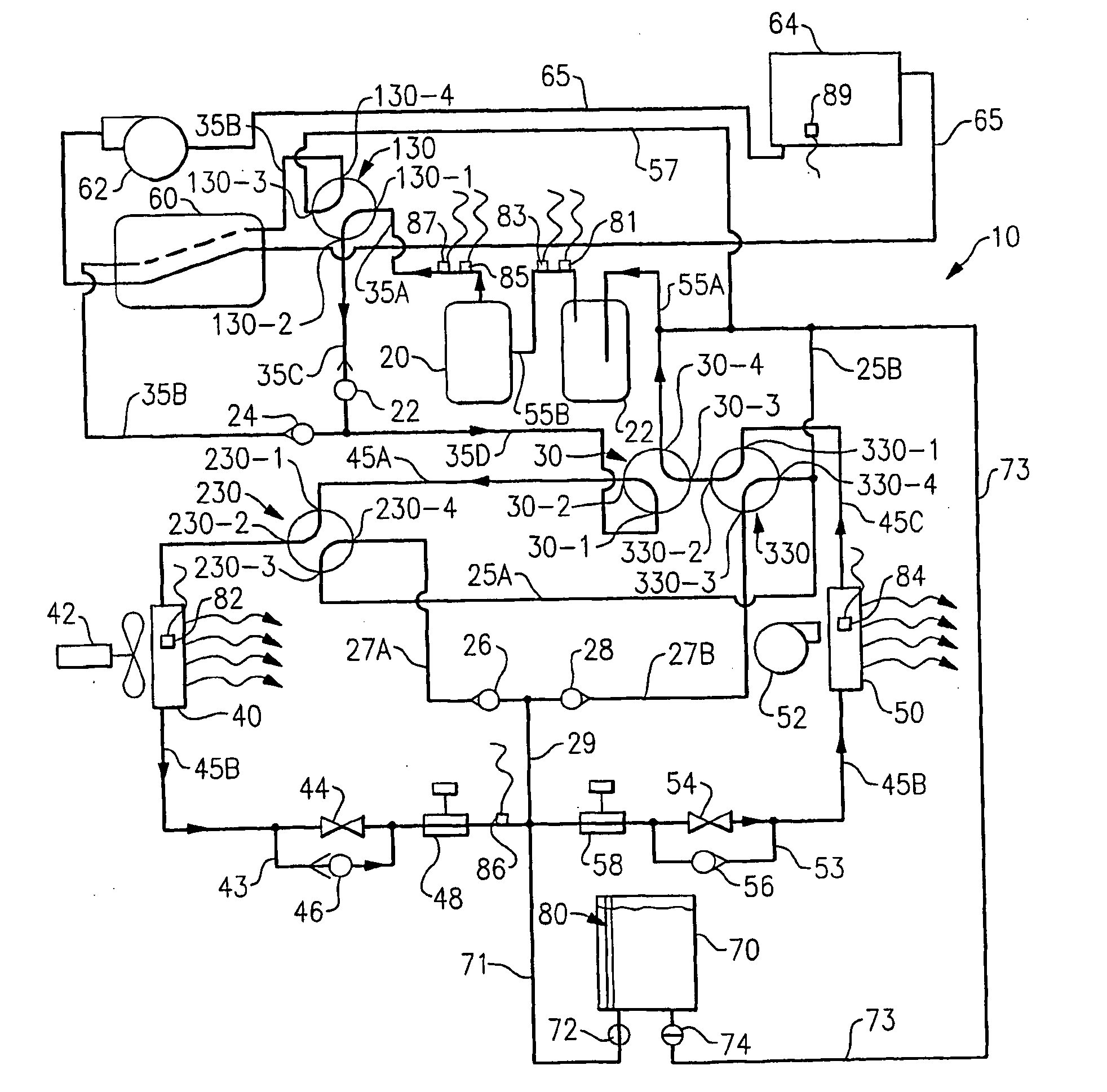
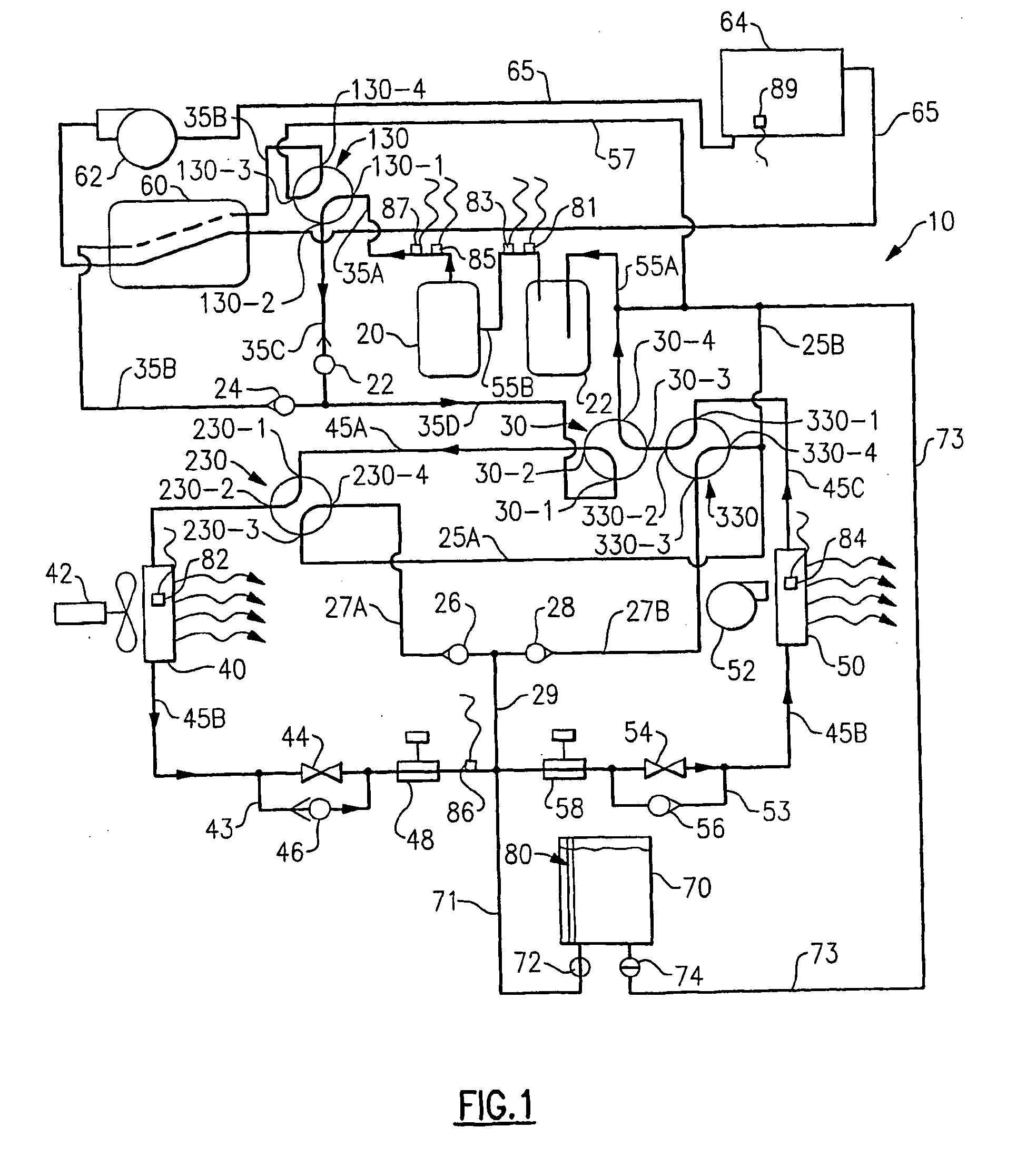
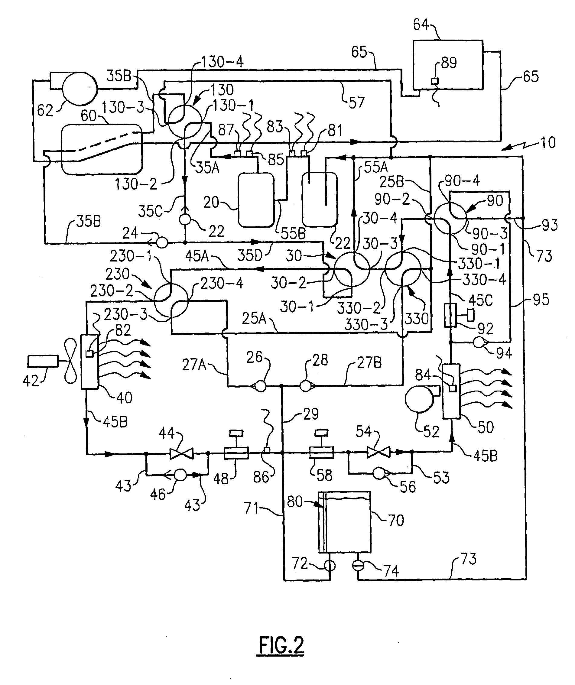
[0035]The refrigerant heat pump system 10, depicted in a first embodiment in FIGS. 1, 3, 5, 7 and 9 and a second embodiment in FIGS. 2, 4, 6, 8 and 10, provides not only either heating or cooling air to a comfort region, for example an indoor zone located on the inside of a building (not shown), but also auxiliary water heating when desired. The system includes a compressor 20, a suction accumulator 22, a reversing valve 30, an outdoor heat exchanger 40 and associated fan 42 located on the outside of the building in heat transfer relation with the surrounding ambient, an indoor heat exchanger 50 and associated fan 52 situated in the comfort zone, a first expansion valve 44 operatively associated with the outdoor heat exchanger 40 and a second expansion valve 54 operatively associated with the indoor heat exchanger 50, a refrigerant-to-water heat exchanger 60, a heat exchanger bypass valve 130, a first bypass / bleed valve 230 and a second bypass / bleed valve 330. A refrigerant circuit ...


PUM


Abstract

A heat pump system (10) includes a compressor (20), a reversing valve (30), an outdoor heat exchanger (40) and an indoor heat exchanger (50) coupled via refrigerant lines (35, 45, 55) in a conventional refrigeration circuit, a refrigerant to liquid heat exchanger (60), a refrigerant to liquid heat exchanger bypass valve (130), an outdoor heat exchanger bypass valve (230), and an indoor heat exchanger bypass valve (330). A controller (100) is provided to selectively control the respective positioning of the valves (30, 130, 230 and 330) between their respective open and closed positions so as to selectively configure the refrigerant circuit for operation in one of an air cooling only mode, an air cooling with liquid heating mode, an air heating only mode, an air heating with liquid heating mode, and a liquid heating only mode.

Description

CROSS-REFERENCE TO RELATED APPLICATIONS[0001]This application relates to the following related applications: International Patent Application No. PCT / BR05 / 00097, filed 3 Jun. 2005 and entitled “HEAT PUMP SYSTEM WITH AUXILIARY WATER HEATING”; International Patent Application No. PCT / BR05 / 00098, filed 3 Jun. 2005 and entitled “REFRIGERANT CHARGE CONTROL IN A HEAT PUMP SYSTEM WITH WATER HEATING”; and International Patent Application No. PCT / BR05 / 00099, filed 3 Jun. 2005 and entitled “REFRIGERANT SYSTEM WITH WATER HEATING”, each of which applications is, together with this application, subject to assignment to a common assignee.TECHNICAL FIELD[0002]This invention relates generally to heat pump systems and, more particularly, to heat pump systems including auxiliary liquid heating, including for example heating water for swimming pools, household water systems and the like.BACKGROUND ART[0003]Reversible heat pumps are well known in the art and commonly used for cooling and heating a clim...

Claims


Application Information

Patent Timeline
IPC IPC(8): F25B30/00
CPCF24D3/08F25B13/00F25B29/003F25B2700/04F25B2339/047F25B2345/001F25B2400/16F25B2313/02743
Inventor MURAKAMI, TOSHIOTESCHE, CARLOS A.FERNANDEZ, ROBERTO G.
Owner CARRIER CORP
Why Eureka
Try Eureka