Method and apparatus for sample injection in liquid chromatography

a liquid chromatography and sample technology, applied in bends, instruments, transportation and packaging, etc., can solve the problems of liquid pressure in the fluid circuit upstream of the obstruction, significant flow and pressure transients in the mobile phase stream, and temporary blockage of the flow path between the pump and the column

Active Publication Date: 2009-02-26
WATERS TECH CORP
View PDF18 Cites 37 Cited by
  • Summary
  • Abstract
  • Description
  • Claims
  • Application Information

AI Technical Summary

Benefits of technology

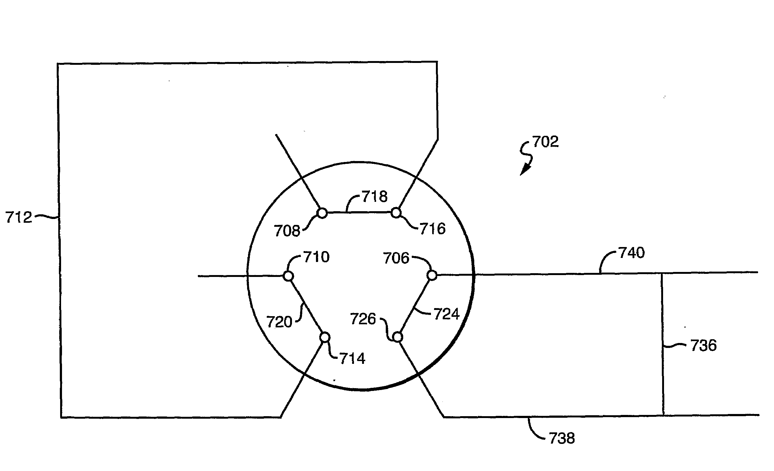
The present invention has several advantages. Firstly, it allows for the elimination of destructive transients of flow rate and pressure by adapting the configurations of rotor channels and stator ports. Secondly, it allows for the control of the direction of compression and decompression of sample loop contents during the injection and removal process, which improves the accuracy and efficiency of the analysis.

Problems solved by technology

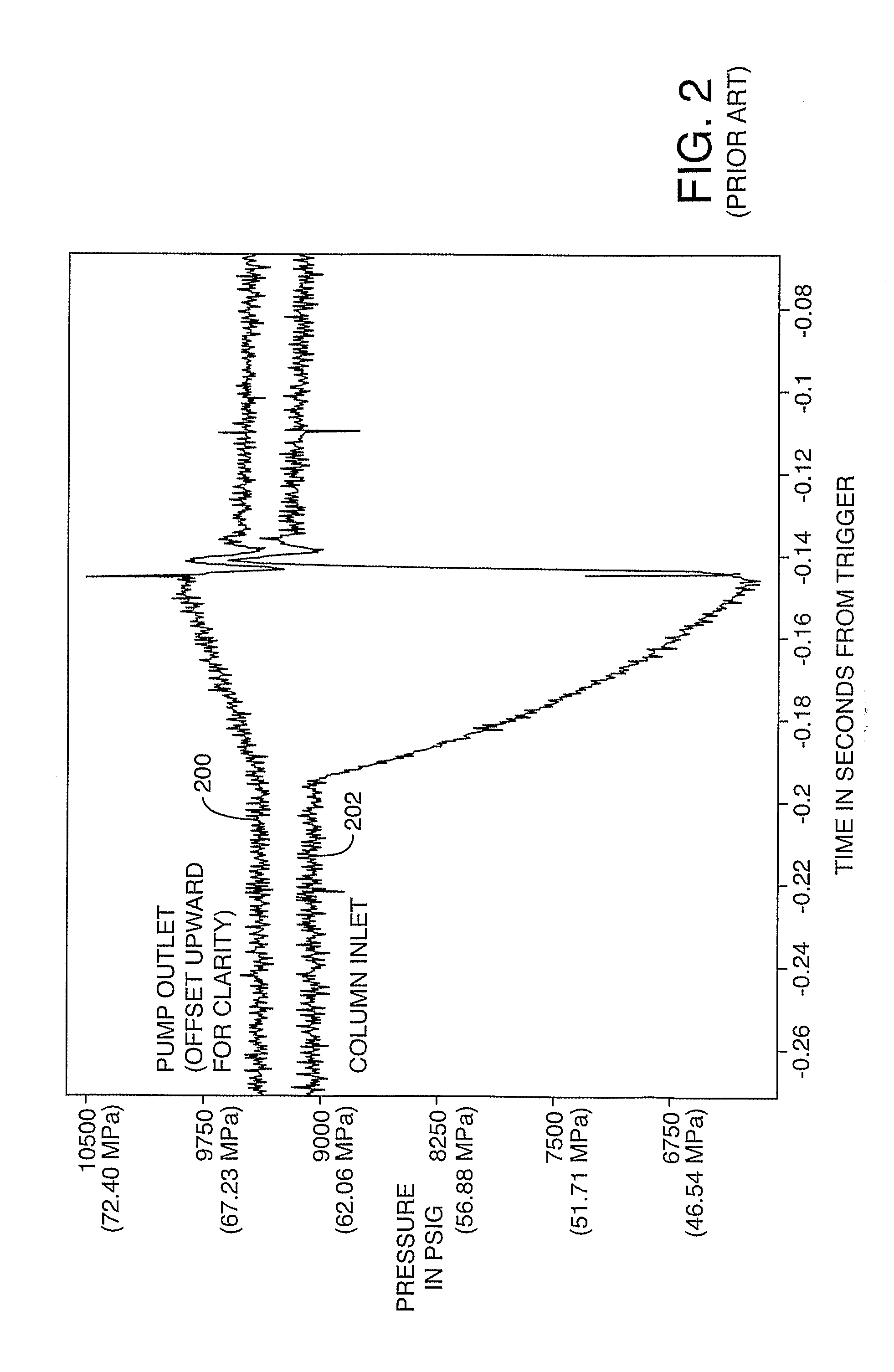
The technical problem addressed in this patent text is the temporary blockage of flow caused by the actuation of valves in high performance liquid chromatography (HPLC) or very high pressure liquid chromatography (VHPLC) systems, which can lead to disruptive effects on the separation of columns and the overall system resistance to flow. The patent text describes various techniques to mitigate the transients caused by the actuation of valves, including the use of resistive bypass injectors and the introduction of a new sample injector design. However, these techniques have limitations and drawbacks, and the overall system resistance to flow can change during the transition between different operating conditions. The patent text also discusses the issue of flow blockage and its impact on the separation of chromatograms in HPLC and VHPLC systems. The loop charging transient is the dominant transient associated with sample injection, and can cause damage to the column. The resistive bypass injector is more complex and expensive to manufacture and may not be the preferred solution in resisting the need for some applications.

Method used


Image

  • Method and apparatus for sample injection in liquid chromatography
  • Method and apparatus for sample injection in liquid chromatography
  • Method and apparatus for sample injection in liquid chromatography

Examples


Embodiment Construction

[0056]Detailed embodiments of the present invention are disclosed herein, however, it is to be understood that the disclosed embodiments are merely exemplary of the invention, which may be embodied in various forms. Therefore, specific functional details disclosed herein are not to be interpreted as limiting, but merely as a basis for the claims and as a representative basis for teaching one skilled in the art to variously employ the present invention in virtually any appropriately detailed embodiment.

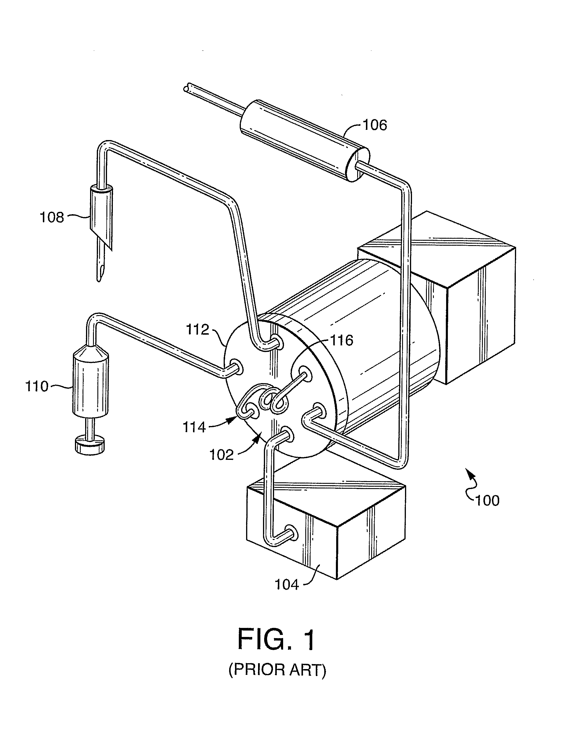
[0057]Turning to FIG. 1, a simplified block diagram of a standard arrangement of an HPLC system 100 utilizing a rotary shear-seal injection valve 102 is shown. Rotary shear seal injection valve 102 is connected to a mobile phase pump 104. The pump 104 delivers mobile phase liquid through selected internal fluid pathways of rotary shear seal injection valve 102. A separation column 106 is also connected to the rotary shear seal injection valve. Separation column 106 acts in concert with...


PUM


Abstract

The present invention provides a method and apparatus for substantially eliminating destructive transients of pressure or flow rate which can degrade the efficiency and useful lifetime of chromatography columns. The present invention enables a substantially constant flow of mobile phase liquid to be maintained through the chromatography system by eliminating the flow blockage interval associated with the actuation of sample injection valves. The present invention further provides a method to reduce the pressure and flow rate transients associated with pressurization of the sample loop contents when the sample loop is introduced to chromatography system delivery pressure.

Description


Claims


Application Information

Patent Timeline
Owner WATERS TECH CORP
Why Eureka
Try Eureka