
Power wheelchair

a wheelchair and power technology, applied in the field of wheelchairs, can solve the problems of user standing on the pedal, b>15/b> falling down or being hurt by the seat, b>1/b> being unsafe in use, and b>15/b> being unable to meet the needs of users, etc., and achieve the effect of improving safety in us

Inactive Publication Date: 2009-02-26
MERITS HEALTH PRODS
View PDF4 Cites 14 Cited by
  • Summary
  • Abstract
  • Description
  • Claims
  • Application Information

AI Technical Summary

Benefits of technology

[0007]The present invention has been accomplished in view of the above-noted circumstances. It is one objective of the present invention to provide a power wheelchair, which has the advantage of safety in use.

Problems solved by technology

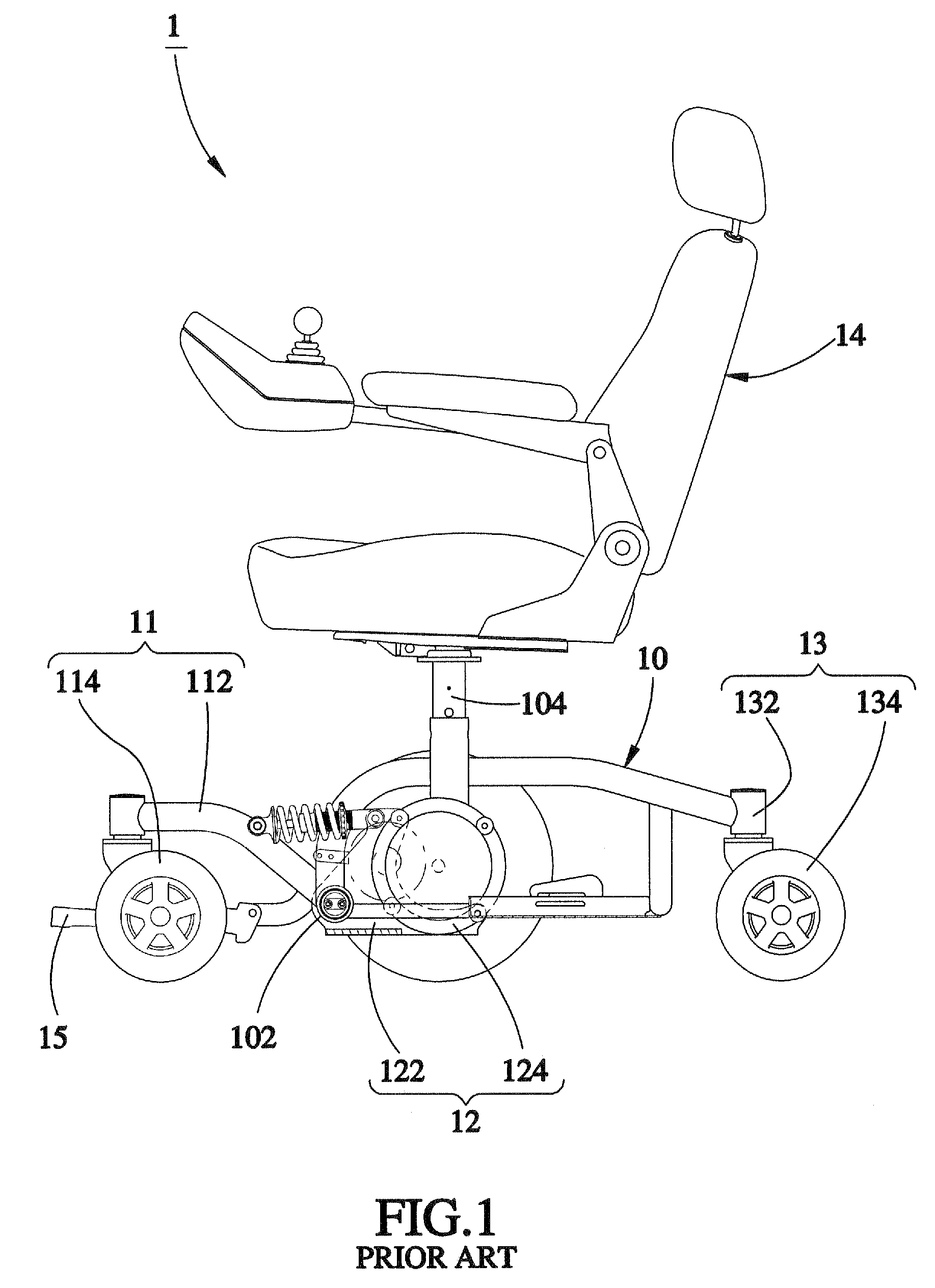
As a result, the user stood on the pedal 15 may fall down or be hurt by the seat set 14.
Thus, the conventional power wheelchair 1 is not safe in use and easily causes an accident to the user.

Method used


Image

  • Power wheelchair
  • Power wheelchair
  • Power wheelchair

Examples


Embodiment Construction

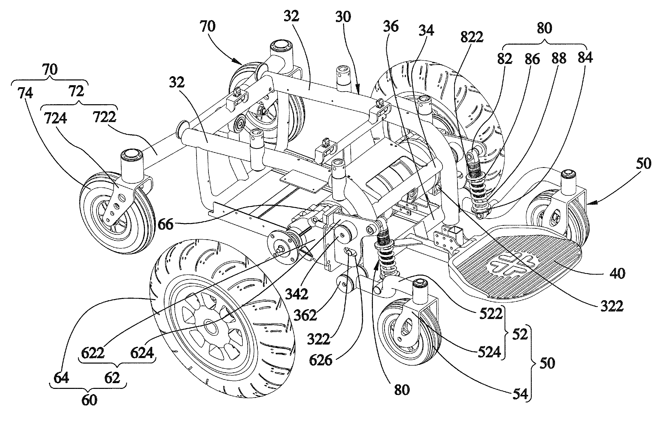
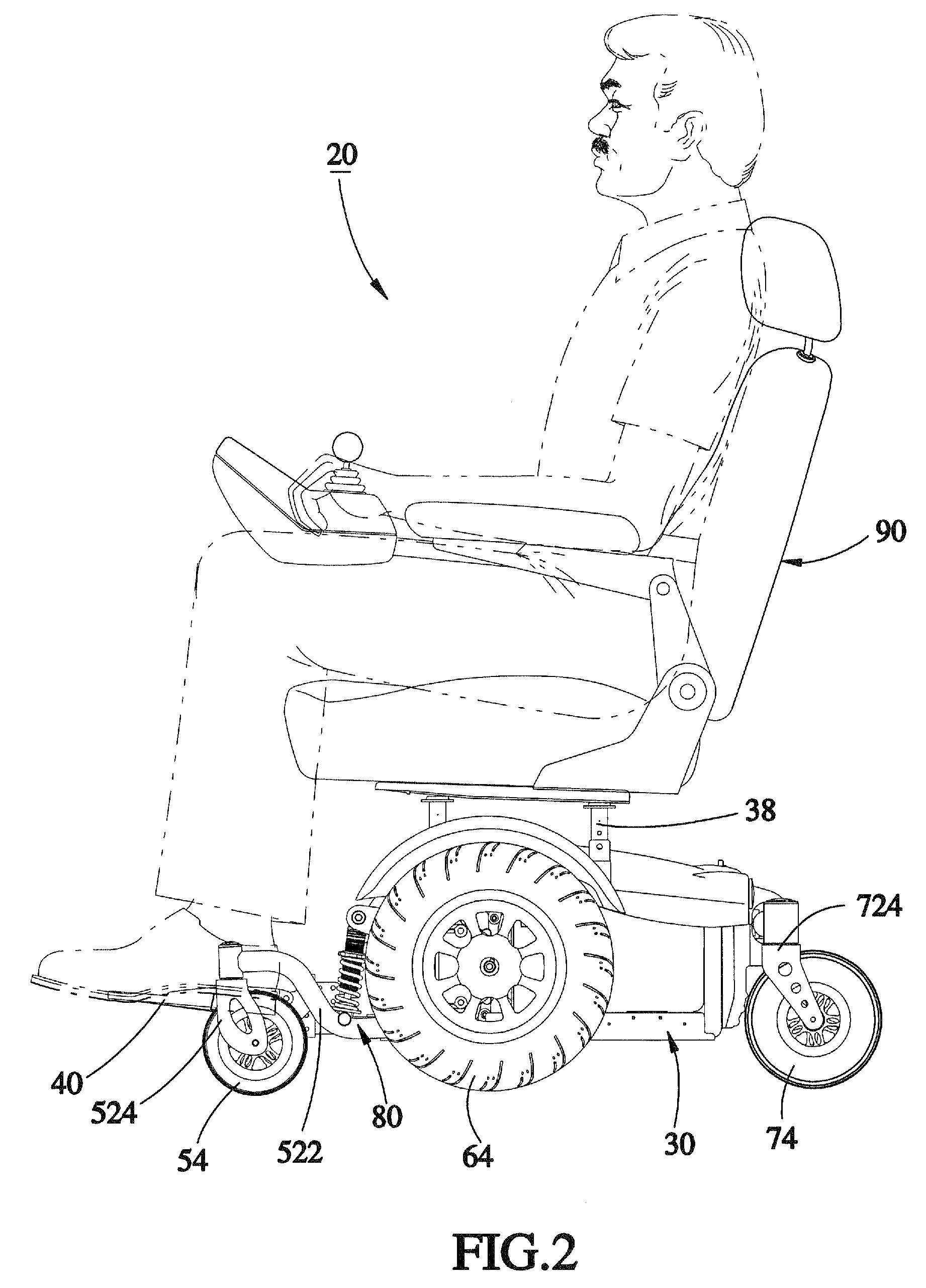
[0016]Referring to FIGS. 2 and 3, a power wheelchair 20 in accordance with a preferred embodiment of the present invention comprises a frame 30, a pedal 40, a pair of first wheel sets 50, a pair of driving wheel sets 60, a pair of second wheel sets 70 and a pair of suspension devices 80.

[0017]The frame 30 has a lateral bar 32 on left and right sides thereof, two limiting portions 322 respectively fixed on a front of the lateral bar 32 with an end extending out of the lateral bar 32, a first bar 34 fixed on the fronts of the lateral bars 32 with two ends respectively protruding out of the lateral bars 32 to form first pivot portions 342, and a second bar 36 fixed on the fronts of the lateral bars 32 and located under the first bar 34 and having two ends respectively protruding out of the lateral bars 32 to form second pivot portions 362. In addition, the frame 30 further includes a plurality of support bars 38 extending upwardly for mounting a seat set 90.

[0018]The pedal 40 is config...


PUM


Abstract

A power wheelchair includes a frame having first and second pivot portions on each of opposite sides of one end thereof, a pair of first wheel sets each having a first wheel mount pivoted to one of the second pivot portions of the frame and a first wheel rotatably connected to the first wheel mount, a pair of driving wheel sets each having a driving wheel mount pivoted to one of the first pivot portions of the frame and a driving wheel rotatably connected to the driving wheel mount, and a pair of suspension devices each connected between the first wheel mount of one of the first wheel sets and the driving wheel mount of one of the driving wheel sets. Thus, the power wheelchair has advantages of stable construction and safety in use.

Description

BACKGROUND OF THE INVENTION[0001]1. Field of the Invention[0002]The present invention relates generally to a power wheelchair, and more specifically to a power wheelchair that has the advantage of safety in use.[0003]2. Description of the Related Art[0004]FIG. 1 shows a conventional power wheelchair 1 comprising a frame 10, a pair of front wheel sets 11, a pair of middle wheel sets 12 and a pair of rear wheel sets 13. The frame 10 has a pivot portion 102 on left and right sides of a front thereof and a support tube 104 behind the pivot portion 102 for mounting a seat set 14. The front wheel sets 11 each have a front wheel mount 112 pivotally connected to the pivot portion 102 of the frame 10 and a front wheel 114 rotatably connected to the front wheel mount 112. The middle wheel sets 12 each have a middle wheel mount 122 pivotally connected to the pivot portion 102 of the frame 10 and a middle wheel 124 rotatably connected to the middle wheel mount 122. The rear wheel sets 13 each h...

Claims


Application Information

Patent Timeline
IPC IPC(8): A61G5/10A61G5/04
CPCA61G5/043A61G2005/128A61G5/063A61G5/128
Inventor CHENG, MING-CHUAN
Owner MERITS HEALTH PRODS
Learn More