Radio Communication System and Radio Communication Method

a radio communication system and radio communication technology, applied in the field of radio communication system technology, can solve the problems that the load cannot be distributed by the transfer user, the network suitable for transferring service data cannot be selected for each service used by the terminal, etc., and achieve the effect of avoiding load concentration or congestion

Active Publication Date: 2009-02-26
PANASONIC INTELLECTUAL PROPERTY CORP OF AMERICA
View PDF10 Cites 41 Cited by
  • Summary
  • Abstract
  • Description
  • Claims
  • Application Information

AI Technical Summary

Benefits of technology

[0038]This configuration enables a packet allocation method to be appropriately set even when interworking connection is to be made to an unknown network, because packet allocation processing is performed in both of a mobile network and a wireless LAN.
[0039]The radio communication system according to the present invention enables a packet allocation method to be appropriately set even when interworking connection is to be made to an unknown network, because packet allocation processing is performed in both of a mobile network

Problems solved by technology

However, a network suitable for transferring service data cannot be selected for each service used by the terminal because the terminal is associated with a communication path in one-to-one correspondence in the services described abov

Method used


Image

  • Radio Communication System and Radio Communication Method
  • Radio Communication System and Radio Communication Method
  • Radio Communication System and Radio Communication Method

Examples


first embodiment

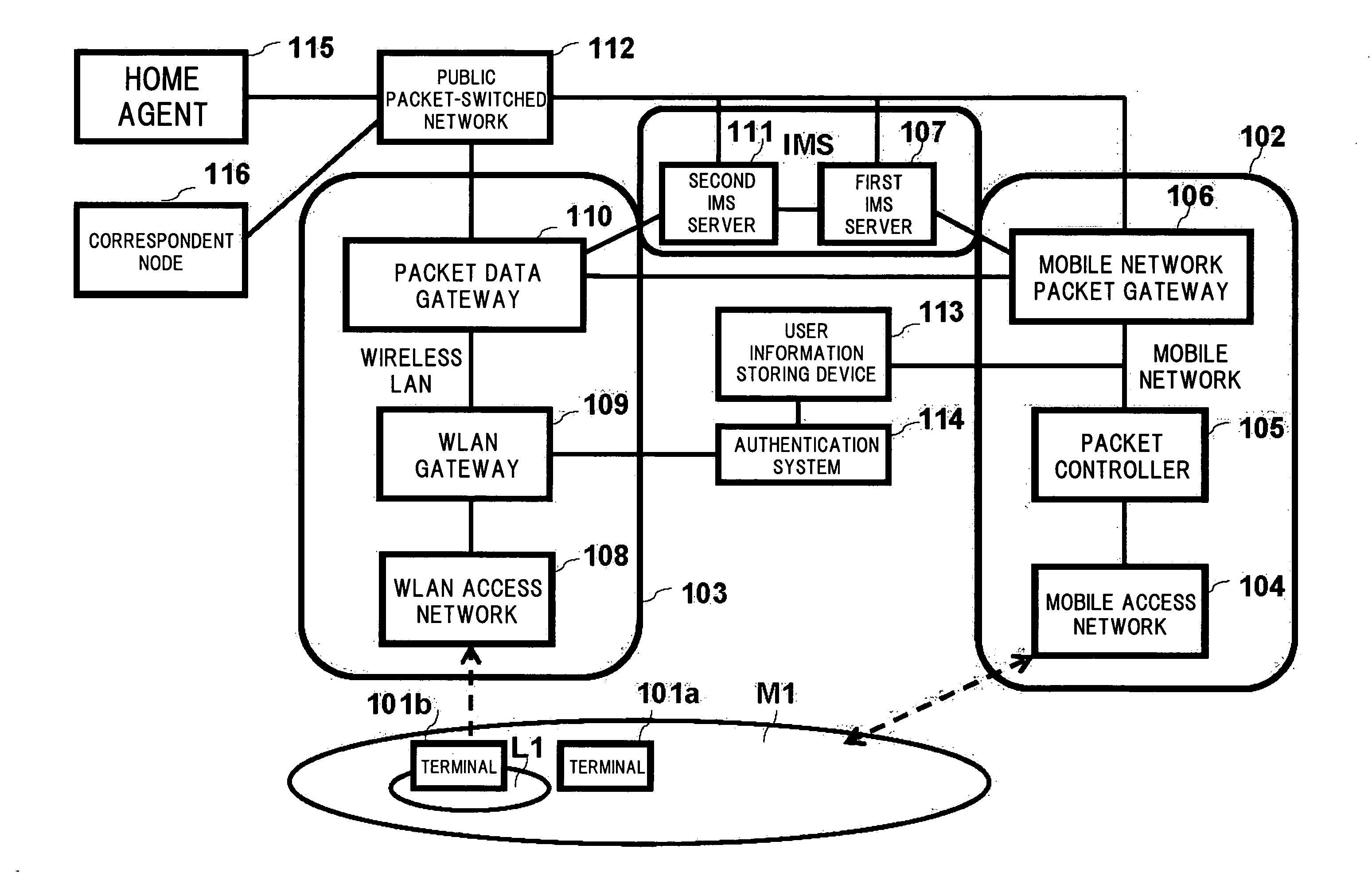
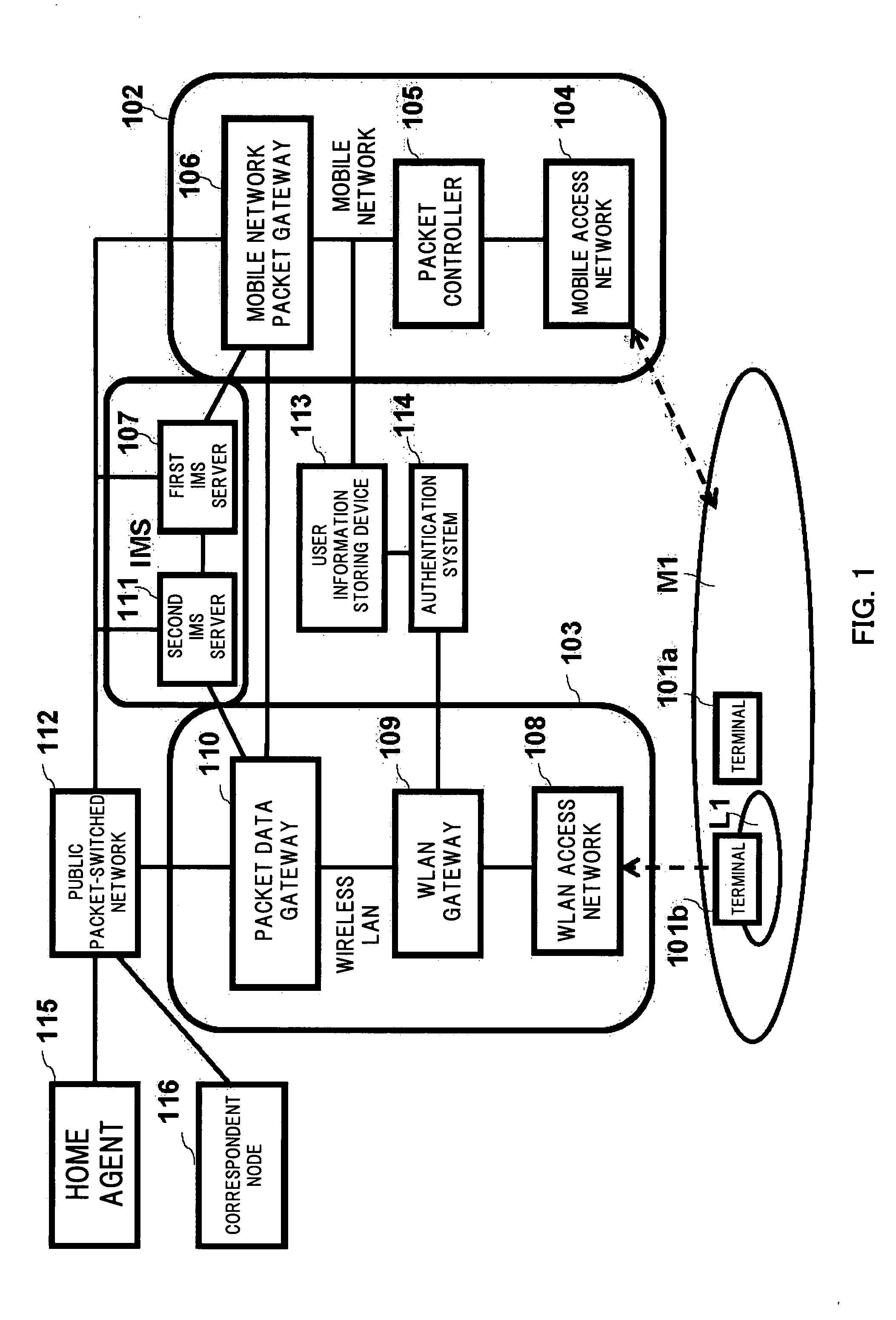
[0063]FIG. 1 is a block diagram showing a system configuration of an interworking system according to a first embodiment of the present invention. In FIG. 1, a terminal 101a in an area M1 and a terminal 101b in an area L1 have an identical configuration and therefore they are sometimes collectively referred to as the terminal 101 herein. The terminal 101 in the first embodiment includes interfaces for communicating with a mobile network 102 and a wireless LAN 103. When communicating with the mobile network 102, the terminal 101 corresponds to UE (User Equipment) in 3GPP.

[0064]In the example shown in FIG. 1, the terminal 101a is in the area (M1) of the mobile network 102. The terminal 101b is in the area (L1) in which the terminal 101b can access both of the mobile network 102 and the wireless LAN 103. In the following description of the embodiment, a process will be described that is performed when the terminal 101 starts communication first in the position of the terminal 101a afte...

second embodiment

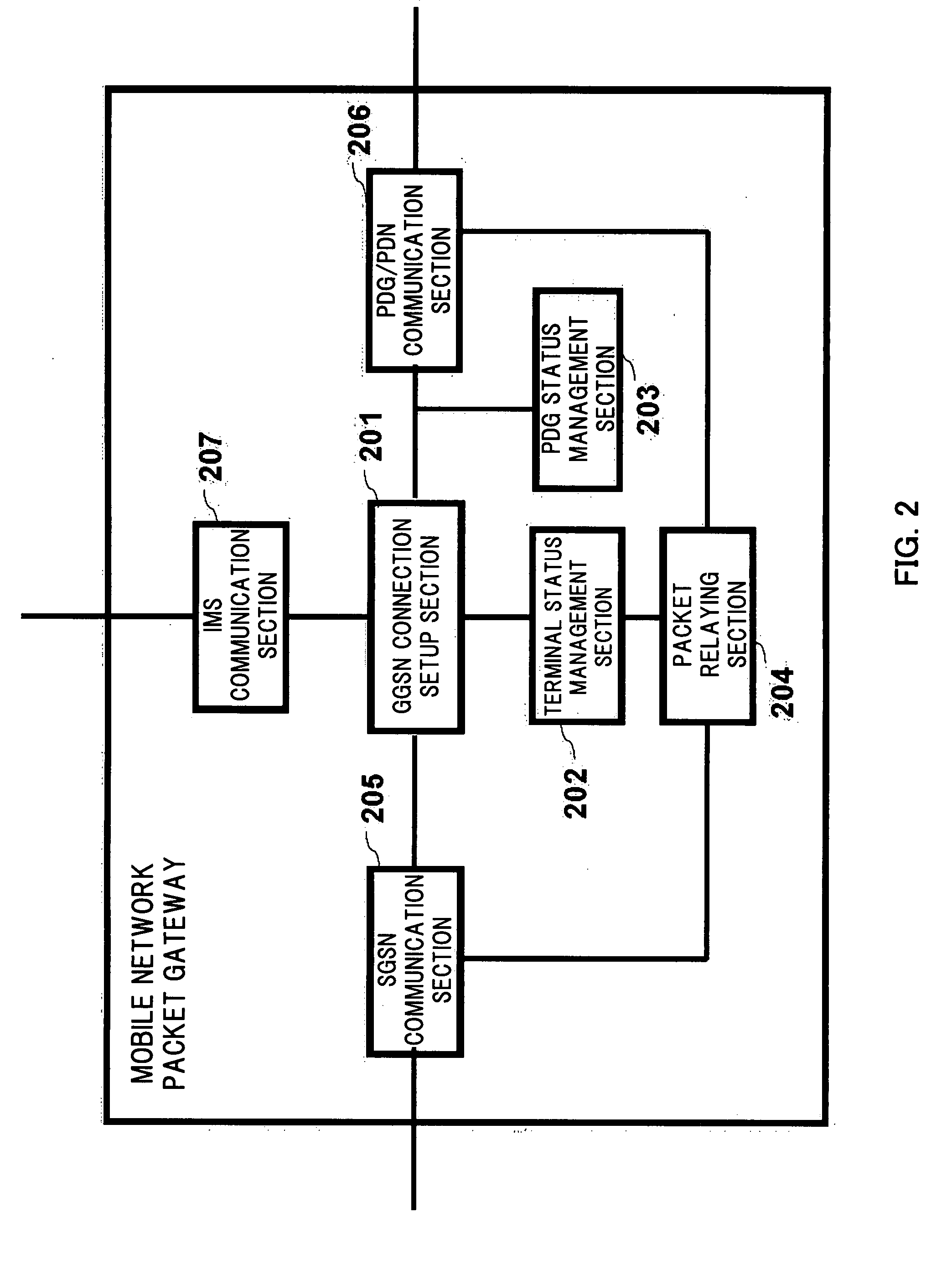
[0175]An interworking system according to a second embodiment has the same system configuration as that of the first embodiment. Therefore, FIGS. 1, 2, and 3 already referred to will be used as block diagrams showing a system configuration of the interworking system, an internal configuration of a mobile network packet gateway, and an internal configuration of a packet data gateway. Operation of the system subsequent to the last state of operation of the system described in the first embodiment will be described below.

[0176]FIG. 18 is a sequence diagram showing operation of a system according to the second embodiment of the present invention. Operation subsequent to the last state of operation of the system described in the first embodiment is shown in the sequence diagram.

[0177]A mobile network packet gateway 106 and a packet data gateway 110 exchange information about each other's operation as operation status exchange 1801 at regular intervals. The operation information is inform...


PUM


Abstract

A terminal (101) includes interfaces for communication with a mobile network (102) and a wireless LAN (103). A first IMS server (107) performs IMS call control processing relating to terminals located in the mobile network (102) and a second IMS server (111) relays a signal relating to IMS call control processing concerning terminals located in the wireless LAN (103). These IMS servers search for a mobile network packet gateway (106), a packet data gateway (110), and a gateway to be controlled by a route change request for requesting change of a packet transmission path and relay the route change request. The route change request provided from the terminal (101) is relayed by the IMS servers to provide the change request to all networks specified. The packet transmission path is changed by the gateway in accordance with the request. Thus, the terminal having the interfaces for both of the mobile communication network and the wireless LAN can select a network to use for each communication port.

Description

BACKGROUND OF THE INVENTION[0001]1. Technical Field[0002]The present invention relates to a radio communication system technology in an interworking system between a mobile communication network and a wireless LAN that enables communications over a mobile communication network and a wireless LAN performed by a terminal having interfaces to both of the communication networks to be optimally allocated between the networks.[0003]2. Background Art[0004]Engineers are working to build a communication system that allows mobile phones capable of communicating in a wide area to interwork with a public wireless LAN service which enables fast data communication in a relatively small area to complement each other. In such a communication system, the following service, for example, can be provided by using a terminal capable of accessing both mobile phone network and wireless local area network (WLAN). A terminal uses a mobile communication network in which an area covered by each base station i...

Claims


Application Information

Patent Timeline
IPC IPC(8): H04W40/00H04W76/02H04W88/06
CPCH04W40/20H04W76/022H04W76/041H04W80/04H04L65/1083H04W92/02H04L65/1016H04L65/1069H04W88/06H04W76/22H04W76/12H04L65/1095
Inventor ISHII, HIDENORISENGA, SATOSHIISHIDA, HIROSHIKANAZAWA, TAKESHI
Owner PANASONIC INTELLECTUAL PROPERTY CORP OF AMERICA
Why Eureka
Try Eureka