Airflow Headgear for a Welding Helmet

Inactive Publication Date: 2009-03-05
ILLINOIS TOOL WORKS INC
View PDF53 Cites 55 Cited by
  • Summary
  • Abstract
  • Description
  • Claims
  • Application Information

AI Technical Summary

Problems solved by technology

Welding can be a heat intensive process, especially during the summer months in outdoor locations or in plants without air conditioning.
The equipment may add to the heat intensive aspects of the welding process and may reduce comfort by allowing air to stagnate, par

Method used


Image

  • Airflow Headgear for a Welding Helmet
  • Airflow Headgear for a Welding Helmet
  • Airflow Headgear for a Welding Helmet

Examples


Embodiment Construction

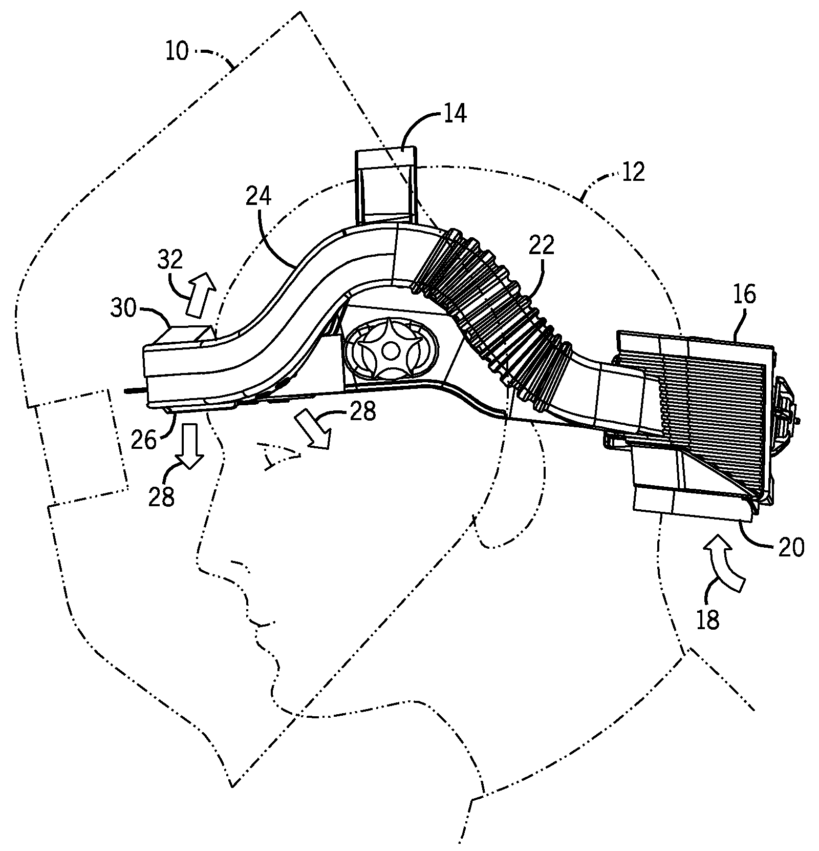
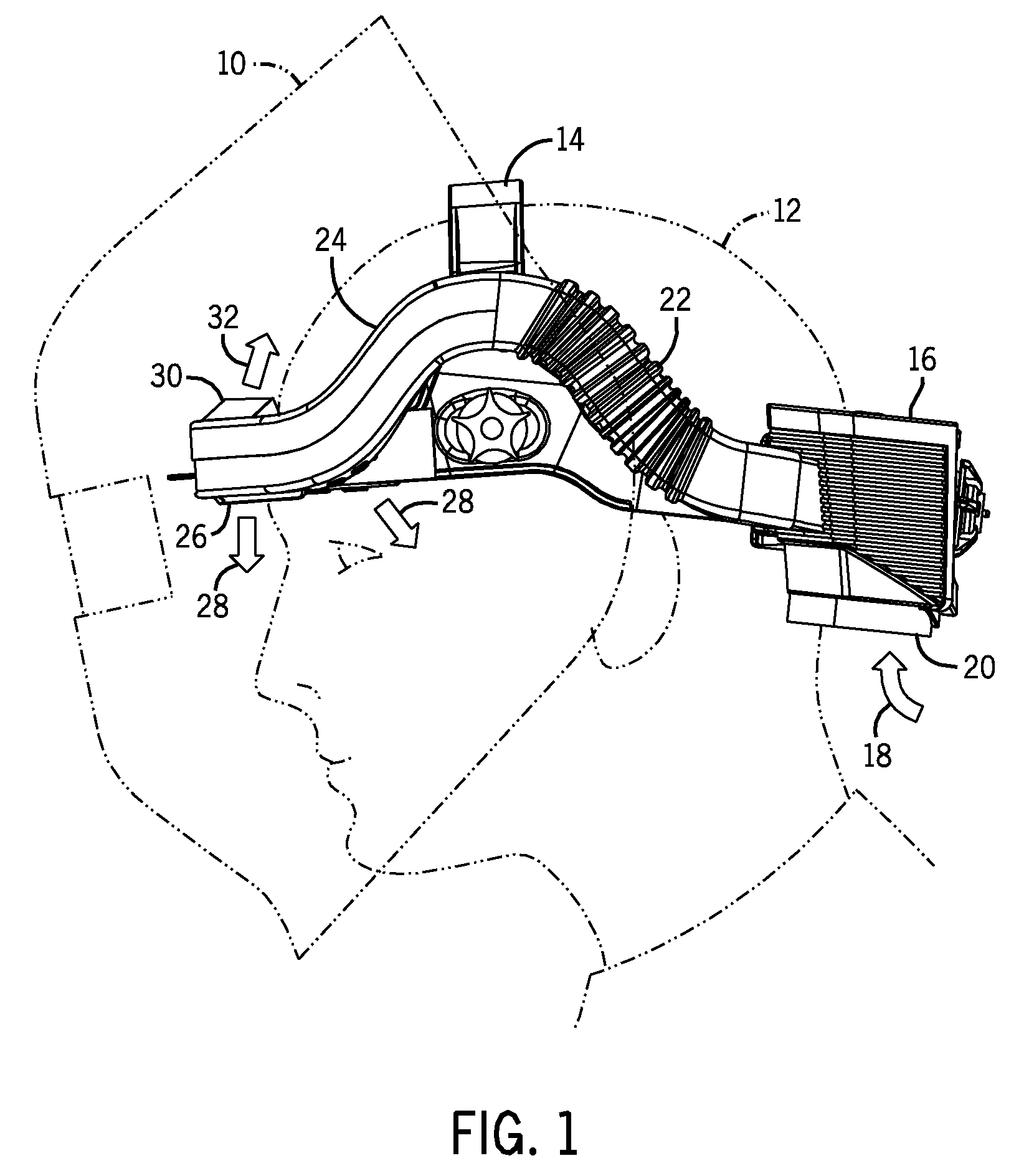
[0021]FIG. 1 illustrates an exemplary welding helmet 10 that incorporates an integrated airflow system in accordance with aspects of the invention. The welding helmet 10 may be constructed of a thermal plastic resin and may cover the face of the welder. The welding helmet 10 may be attached to a headgear 14 that is worn by the wearer or user 12. The headgear 14 generally includes straps that extend around the user's head and over the top of the head to provide support and stability for the welding helmet 10. An airflow system 16 may be attached to or integrated into the headgear 14 and may generally follow the circumference of the headgear 14. In certain embodiments, the airflow system may be permanently attached to the headgear. In such an embodiment, the headgear itself may serve as part of the air conduit. However, in other embodiments, the airflow system may be affixed to the headgear using mounting brackets or other attachment methods. By generally following the circumference o...


PUM


Abstract

An airflow system is provided for a welding helmet. The airflow system includes an air intake with a filter, a blower, and a battery mounted to the rear of headgear for a welding helmet. A manifold wraps around the side and front of the headgear and directs air from the blower to the front of the headgear. The manifold includes a lower vent for directing air onto a user's face and an upper vent for directing air over a user's head toward the rear of the headgear. The vents are intended to create positive pressure to impede the entry of unfiltered air into the user's breathing zone. The manifold further includes a portion of flexible tubing for adjusting the size of the airflow system in conjunction with adjustment of the headgear diameter. The airflow system generally conforms to the structure and shape of the headgear to maintain a location close to the user's head.

Description

CROSS REFERENCE TO RELATED APPLICATIONS[0001]This application is a Non-Provisional Patent Application of U.S. Provisional Patent Application No. 60 / 967,511, entitled “Airflow Headgear for a Welding Helmet,” filed Sep. 5, 2007, which is herein incorporated by reference.BACKGROUND[0002]The invention relates generally to airflow systems for welding helmets.[0003]Welding can be a heat intensive process, especially during the summer months in outdoor locations or in plants without air conditioning. Further, welders typically wear equipment, such as leather gloves, long sleeve jackets, and welding helmets to cover the eyes, face, and neck. The equipment may add to the heat intensive aspects of the welding process and may reduce comfort by allowing air to stagnate, particularly around a welder's face. Further, the welding process may generate smoke, fumes, and various gases that add to the discomfort of welders.[0004]Various arrangements have been devised in attempts to provide cooling and...

Claims


Application Information

Patent Timeline
IPC IPC(8): A61F9/06A42C5/04A42B1/24
CPCA61F9/068A62B18/003A62B18/006A62B18/04
Inventor BECKER, WILLIAMDOBSON, KENNETH S.KWOK, KUI-CHIUSOMMERS, ERIC
Owner ILLINOIS TOOL WORKS INC
Why Eureka
Try Eureka