Supporting pad for high heels

Inactive Publication Date: 2009-03-05
CHEN WEN LUNG
View PDF7 Cites 5 Cited by
  • Summary
  • Abstract
  • Description
  • Claims
  • Application Information

AI Technical Summary

Benefits of technology

[0006]An objective of the invention is to solve the above-mentioned problems by providing a supporting pad for high heels. The top surface of the pad body has a heel part, an arc part, and a concave part, all designed according to the curve of the foot bottom. The pad is in close contact with the

Problems solved by technology

After a long time, the metatarsus 92 and the heel 93 continuously receive different

Method used


Image

  • Supporting pad for high heels
  • Supporting pad for high heels
  • Supporting pad for high heels

Examples


Example

[0018]The present invention will be apparent from the following detailed description, which proceeds with reference to the accompanying drawings, wherein the same references relate to the same elements.

[0019]FIGS. 1 to 5 show the structure of an embodiment of the invention. They are used as an example for the purpose of explaining the spirit of the invention. The invention is defined by the claims.

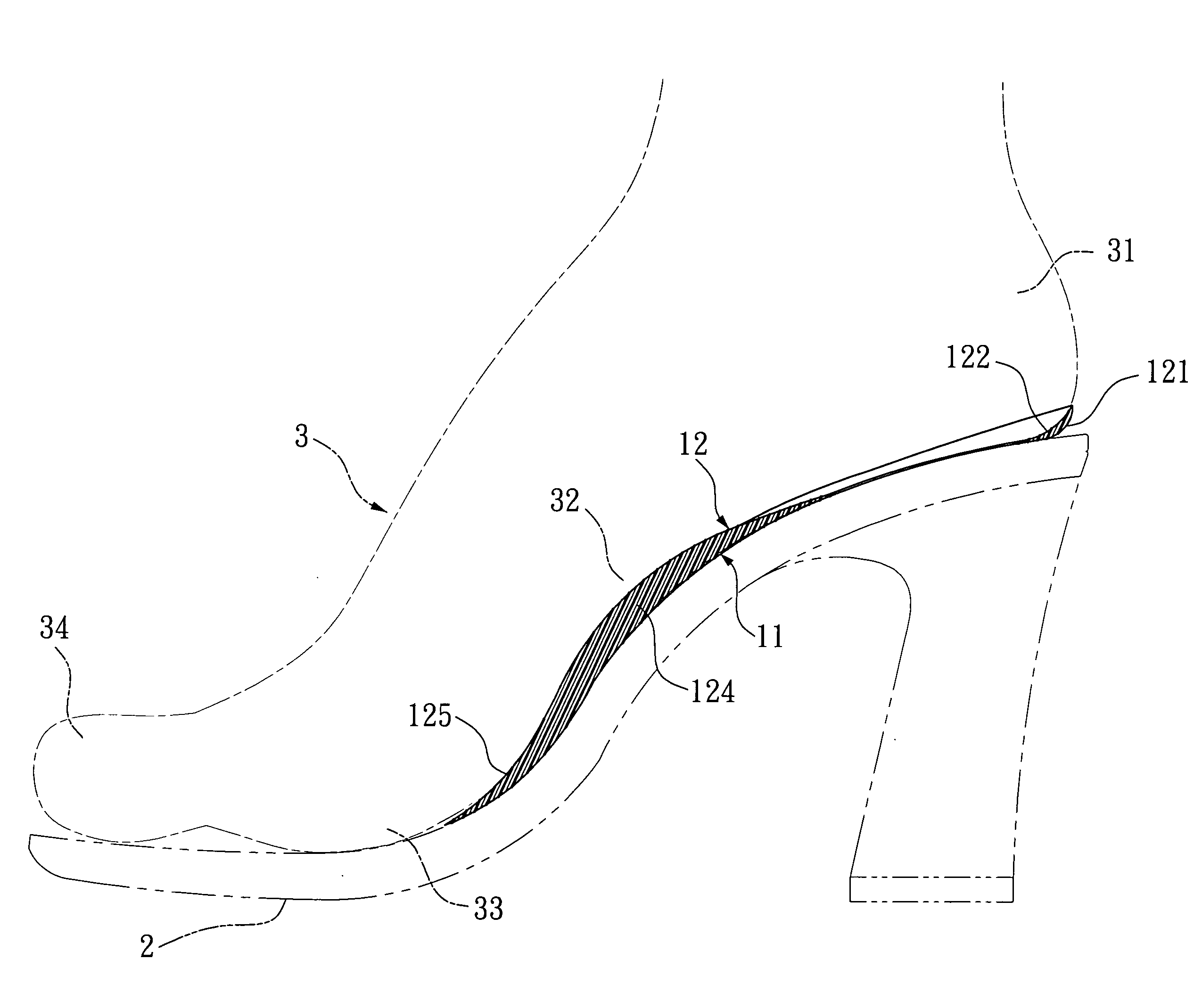
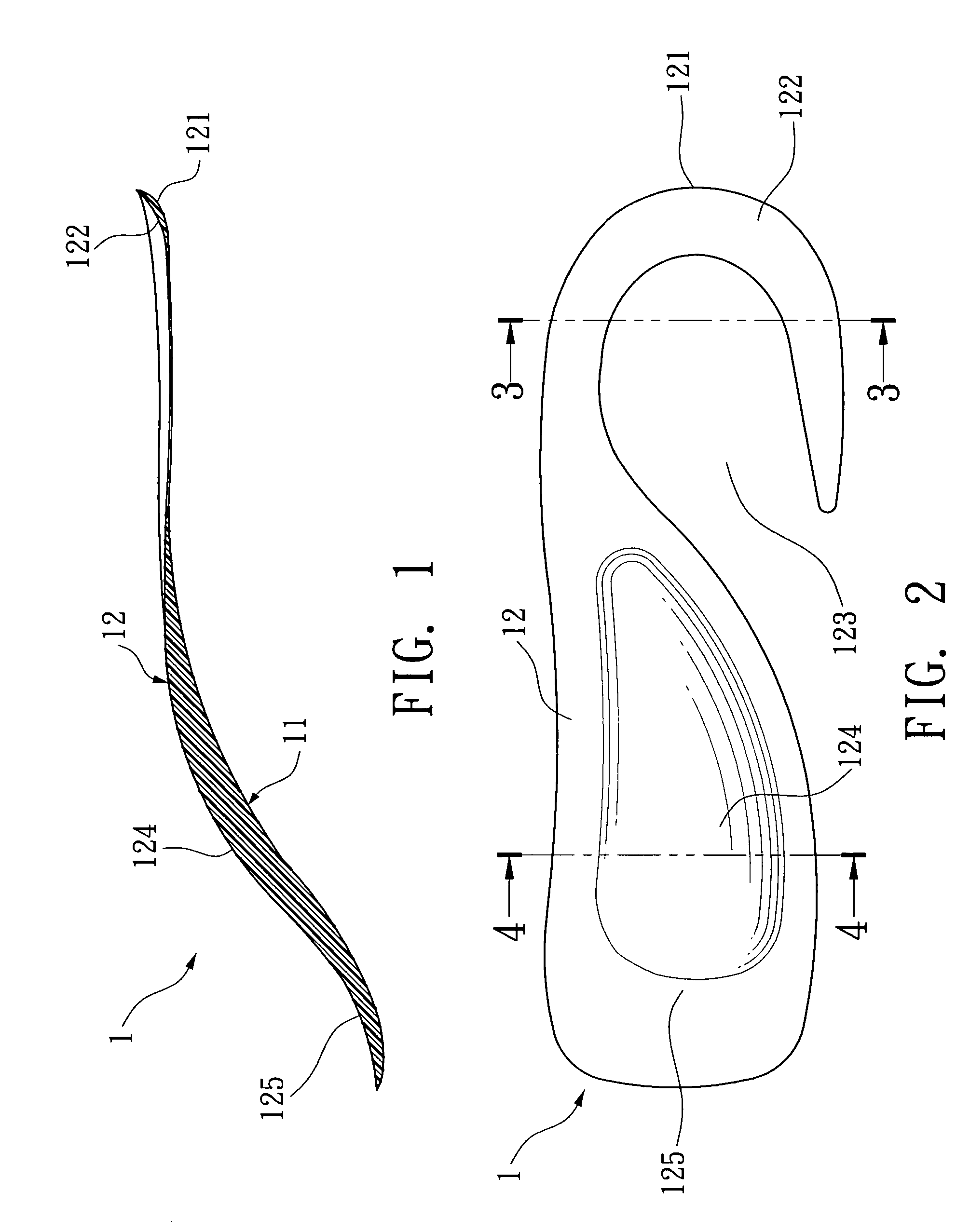
[0020]The supporting pad for high heels according to the preferred embodiment of the invention includes a body 1, a heel part 121, and an arc part.

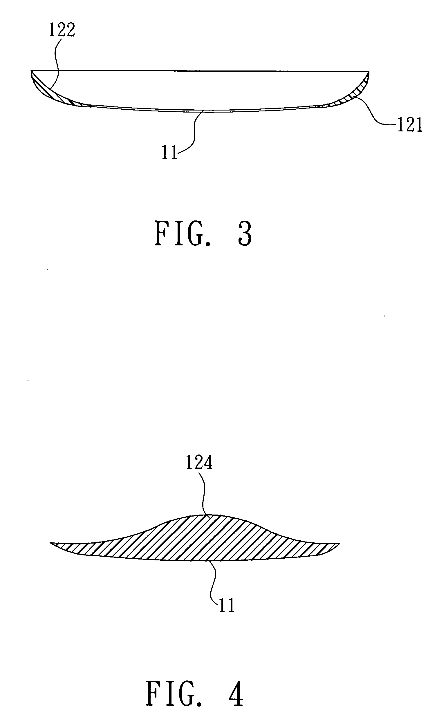
[0021]The body 1 has a bottom surface 11 and a top surface 12. The bottom surface 11 is a flat contact surface, completely in touch with the sole 2 of the high heel. The top surface 12 is designed according to the curve of the human foot bottom.

[0022]The heel part 121 is disposed on the top surface 12. The heel part 12 has a shape that fits the shape of the heel 31, higher on two sides and lower in the central portion, forming a concave structur...


PUM


Abstract

A supporting pad for high heels has a heel part, an arc part, and a concave portion on the top surface of its body. Each part is designed according to the curve of the human foot, so as to in close contact with the heel, the foot arc, and the metatarsus between the foot arc and the toes. The bottom surface of the body is also tightly attached to the sole of the high heel. Such a support provides a stable and balanced surface at the bottom of user's feet. This complete support can effectively distribute pressure imposed on the foot and relieve discomfort due to the impacts.

Description

BACKGROUND OF THE INVENTION[0001]1. Field of Invention[0002]The invention relates to a supporting pad for high heels and, in particular, to a supporting pad that helps forming a stable surface for the feet of the person who wears the shoes, effectively dissipating pressure on the feet and alleviating uncomfortable impacts thereon.[0003]2. Related Art[0004]As shown in FIG. 6, the shoe bottom 8 of usual high heels sold on the market has a plane design. Due to the shape of foot bones, the foot bottom of normal people is not completely flat. In particular, the arc of foot 91 is not in close contact with the sole 8 of the shoe. Therefore, the user's foot bottom does not completely rest on the sole 8.[0005]When the user walks for a long distance with the high heels, the pressure from the sole 8 cannot be evenly distributed over the foot bottom 9. After a long time, the metatarsus 92 and the heel 93 continuously receive different pressures or some region receives too large a pressure, resu...

Claims


Application Information

Patent Timeline
IPC IPC(8): A43B13/38
CPCA43B7/141A43B7/142A43B17/02A43B7/1445A43B7/144
Inventor CHEN, WEN-LUNG
Owner CHEN WEN LUNG
Why Eureka
Try Eureka