Floor Vent Booster Fan

Inactive Publication Date: 2009-03-05
GRACIOUS LIVING CORP
View PDF19 Cites 28 Cited by
  • Summary
  • Abstract
  • Description
  • Claims
  • Application Information

AI Technical Summary

Benefits of technology

[0009]Additional elements can include a switch to activate and deactivate the fan, and an indicator light to signal when the fan is in operation. Other additional elements inc

Problems solved by technology

One of the issues that arise in forced-air heating systems is the difficulty in ensuring adequate airflow into the ventilated area from the ventilation ducts.
In some cases, the resulting airflow at some of all of the vents can be insufficient to provide proper ventilation, or even proper distribution of heating and cooling.
Additionally, access to the fan for repairs or replacement is extremely limited

Method used


Image

  • Floor Vent Booster Fan
  • Floor Vent Booster Fan
  • Floor Vent Booster Fan

Examples


Embodiment Construction

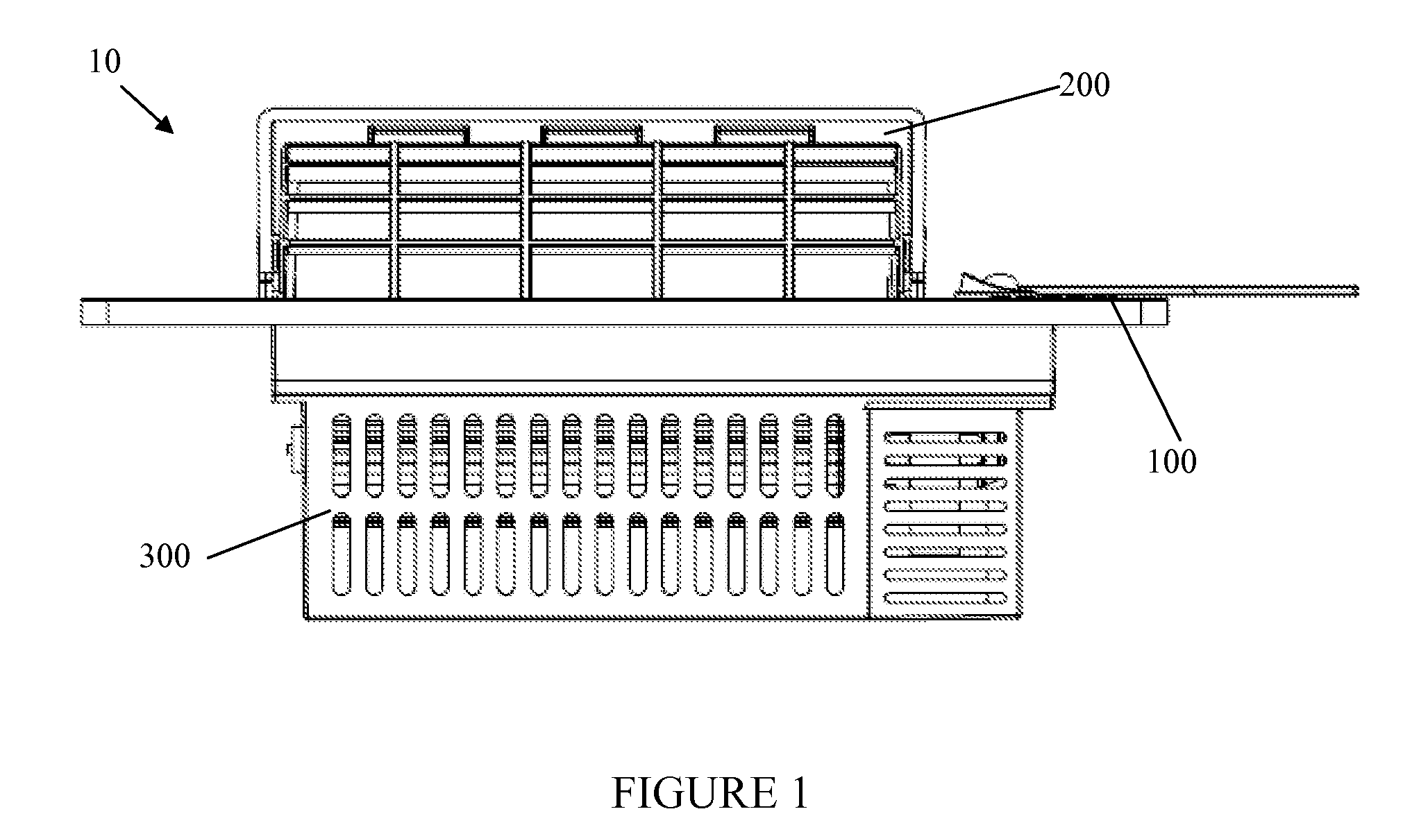
[0018]The inventive apparatus presented herein consists of a floor vent booster fan 10, with a preferred embodiment as shown in FIG. 1. Note that the terms ‘front’, ‘back’ and ‘side’ are used herein for convenience and are not intended to reflect any specific orientation that is required for the booster fan 10.

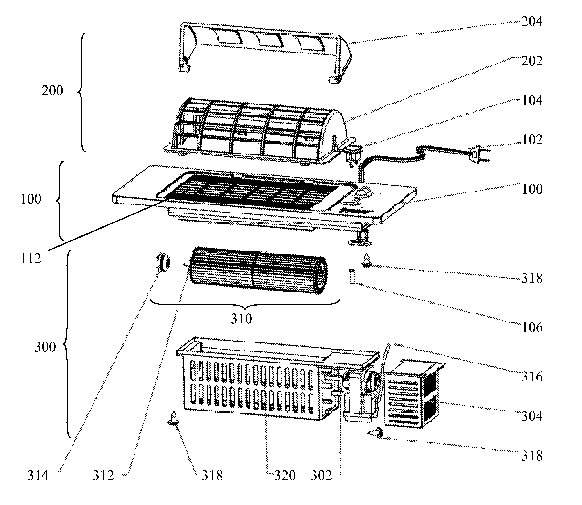
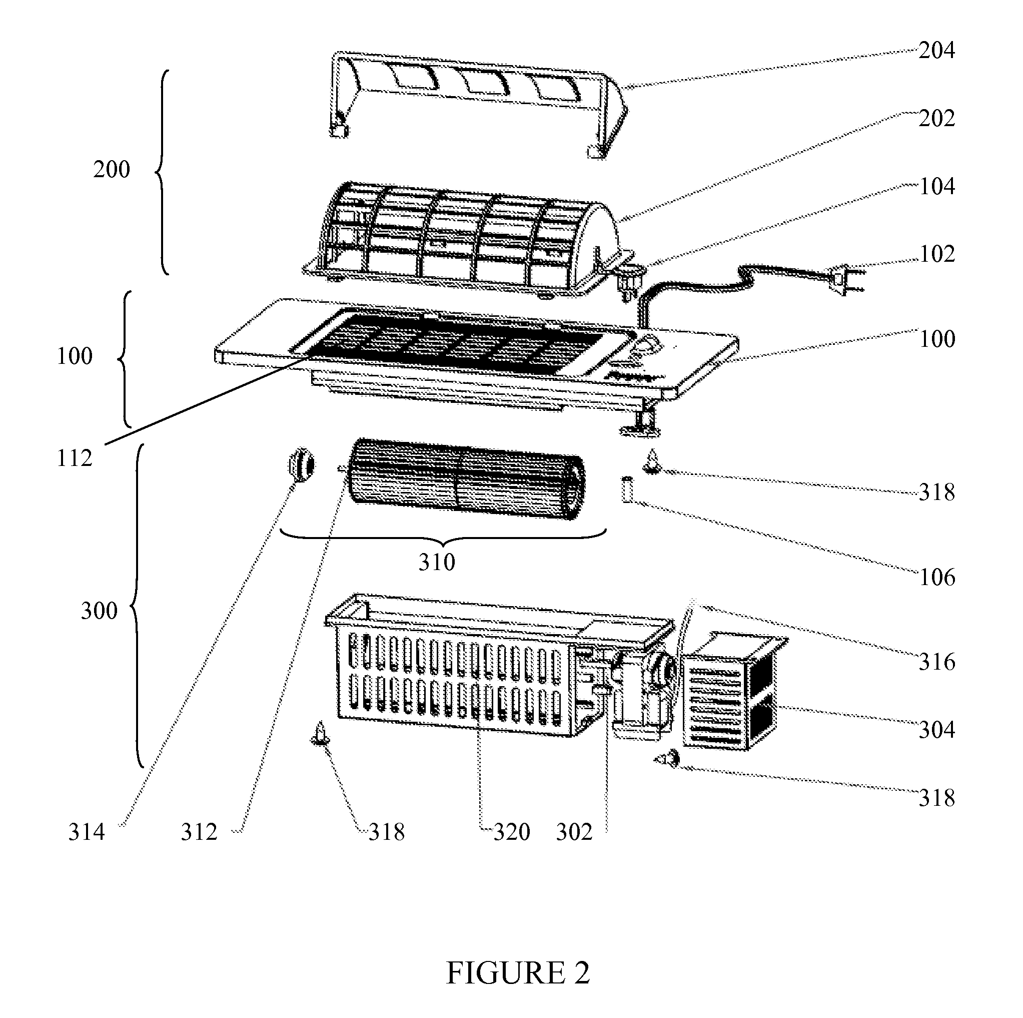
[0019]A presently preferred embodiment of the invention is shown in FIG. 1, with booster fan 10 preferably a unitary assembly that can be identified by three separate sections: vent section 100, deflector section 200 and fan section 300.

[0020]As best shown in FIG. 2, the vent section 100 consists of an outer frame 110 dimensioned to cover the opening into the duct. The outer frame 110 has a slotted opening 112 to permit air flow through the booster fan 10 into and out of the duct (not shown) while blocking the ingress and egress of small objects. The vent section 100 further includes a switch 104 to activate and deactivate the fan motor 302, and a power cord 102 to supply powe...


PUM


Abstract

The invention consists of a vent booster fan, comprising: a) a vent housing, forming a vent which is operable for insertion into a ventilation duct; and defining a vent surface through which air flows from the duct; b) a fan assembly located within the vent housing, containing a fan operative to force air through the vent, the fan assembly located within the vent housing so as to be located substantially within the duct; c) an air deflector covering a portion of the vent surface sufficient to alter airflow from the vent.

Description

FIELD OF THE INVENTION[0001]The present invention relates to the field of vents for airflow systems. In particular, it relates to a combination vent and fan to boost airflow through the vent.BACKGROUND OF THE INVENTION[0002]One of the issues that arise in forced-air heating systems is the difficulty in ensuring adequate airflow into the ventilated area from the ventilation ducts. As the number of air outlets in the ductwork increases, and as the overall length of ductwork increases, the requirements for the starting airflow (i.e. fan power) increase as well. In some cases, the resulting airflow at some of all of the vents can be insufficient to provide proper ventilation, or even proper distribution of heating and cooling. One proposed method of overcoming this problem is through the use of additional ‘booster’ fans in the ductwork.[0003]One type of booster fan, as illustrated by U.S. Pat. No. 6,322,443 to Jackson, discloses a booster fan located in the ductwork behind the vent loca...

Claims


Application Information

Patent Timeline
IPC IPC(8): F24F7/06
CPCF24F7/065
Inventor YEUNG, PETER PO LAMREMME, CHRISTINE ANN
Owner GRACIOUS LIVING CORP
Why Eureka
Try Eureka