Printer-labeler and labeler

a labeler and label technology, applied in the direction of mechanical control devices, instruments, process and machine control, etc., can solve the problems of label tip reaching peeling edge and peeling, label may not be surely removed, and it is impossible to remove the label found defectiv

Inactive Publication Date: 2009-03-12
TOSHIBA TEC KK +1
View PDF8 Cites 7 Cited by
  • Summary
  • Abstract
  • Description
  • Claims
  • Application Information

AI Technical Summary

Benefits of technology

[0015]It is an object of the present invention to positively remov...

Problems solved by technology

However, in case of adopting the technique described in Patent Literature 1 and in case of using a label which is long in the conveyance direction, there arises the problem that when a defect is detected by the RFID reader-writer, the label tip has already reached the peeling edge and peeling started.
In this case i...

Method used


Image

  • Printer-labeler and labeler
  • Printer-labeler and labeler
  • Printer-labeler and labeler

Examples


Embodiment Construction

[0027]A printer-labeler and a labeler both embodying the present invention will be described below with reference to FIGS. 1 to 8.

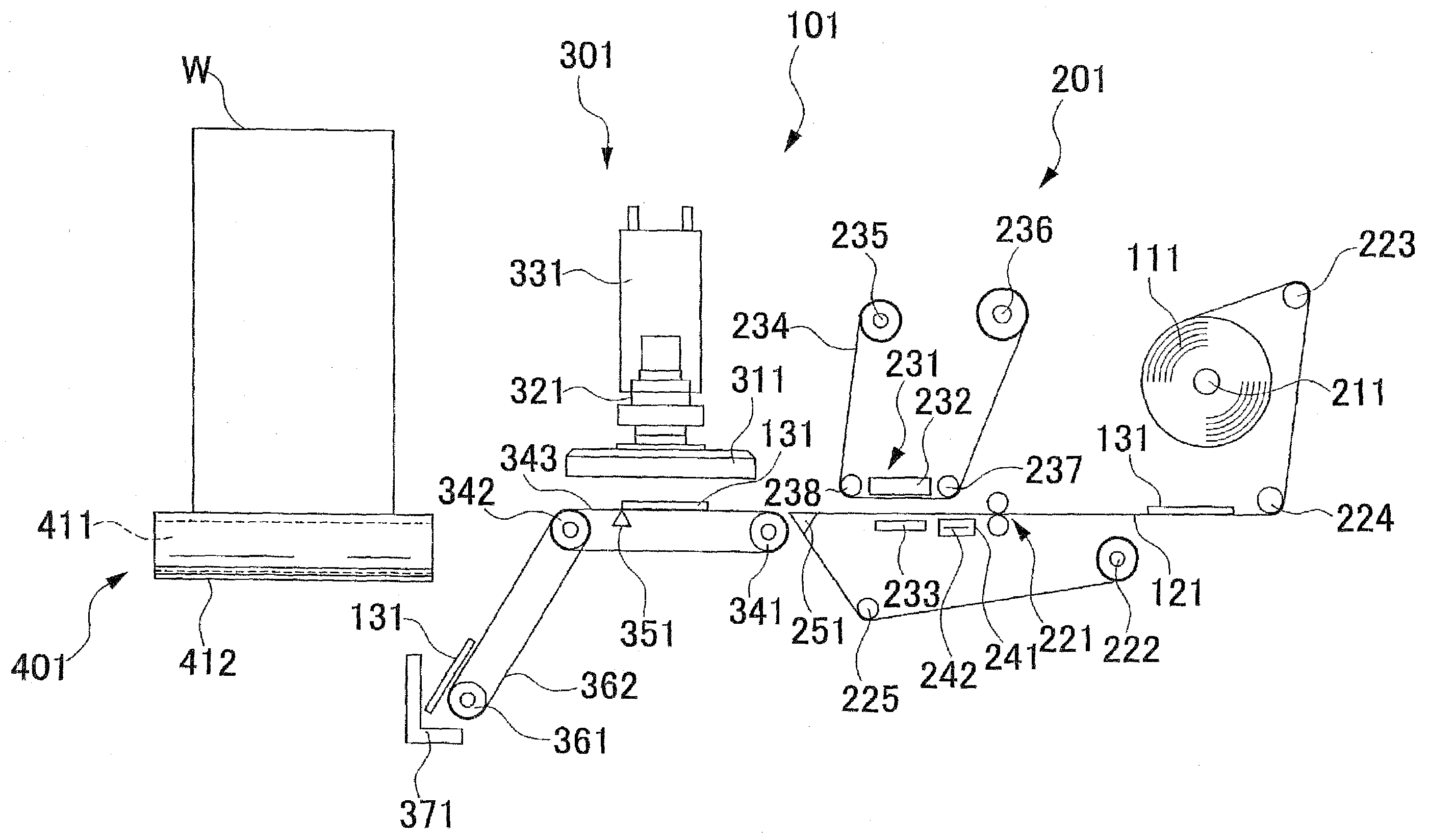
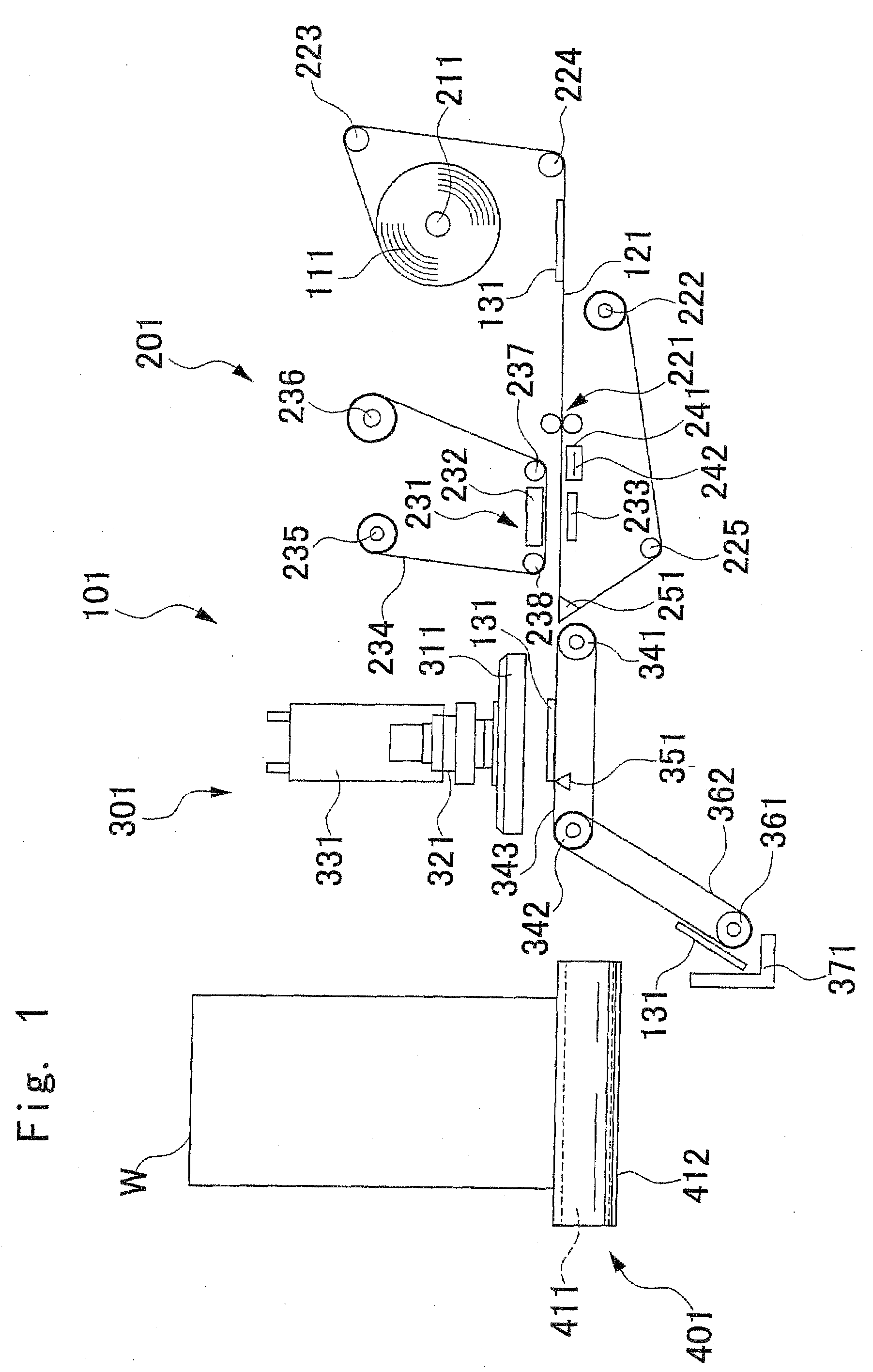
[0028]As shown in FIG. 1, a printer-labeler 101 embodying the present invention is mainly composed of a printer 201 and a labeler 301 which are disposed side by side. A work conveying unit 401 is disposed adjacent to the printer-labeler 101. The work conveying unit 401 conveys a work W, which is an object to which a label 131 is to be stuck, to a position confronting the labeler 301.

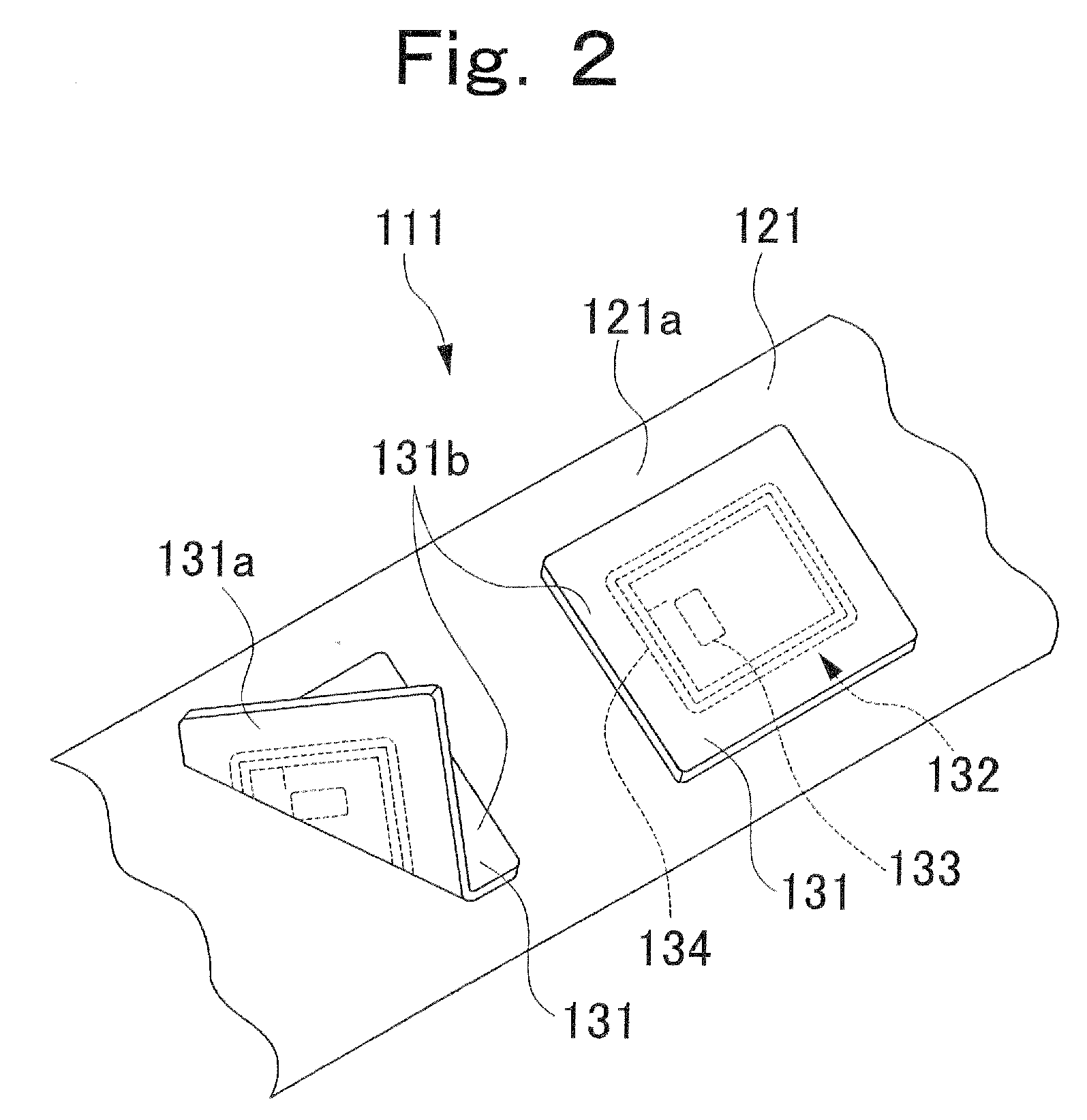
[0029]A description will be given first about the printer 201. Within a housing (not shown) of the printer 201 there is disposed a holding shaft 211 which holds rolled label paper 111 rotatably. The label paper 111 has a construction such that plural labels 131 are arranged at predetermined certain intervals on a long base paper 121 (see FIG. 2).

[0030]The label paper 111 held by the holding shaft 211 is drawn out and conveyed by conveying rollers 221 and is eventually wound up...


PUM


Abstract

When a label on a conveyor belt is detected, there is performed a label sticking process of making a sticking mechanism take out the label and stick it to an article at a predetermined position, while when a defect of the label on the conveyor belt is detected before detecting the label, the label is sent out to a label recovery position without performing the label sticking process.

Description

CROSS REFERENCE TO RELATED APPLICATION[0001]The present application is based on and claims the benefit of priority of Japanese Patent Application No. 2007-188184 filed on Jul. 19, 2007, the entire contents of which is incorporated herein by reference.BACKGROUND OF THE INVENTION[0002]1. Field of the Invention[0003]The present invention relates to a printer-labeler and a labeler.[0004]2. Discussion of the Background[0005]Heretofore there has been known a printer-labeler comprising a printer and a labeler both arranged side by side. In the printer section there are performed write of RFID data for an RFID tag of a label, printing to the label on the basis of printing data, and peeling of the label from base paper by turning up the label with a peeling edge (Japanese Laid-Open Publication No. 2005-119687) (Patent Literature 1). Though not clearly shown in Patent Literature 1, there is known a printer-labeler wherein in the labeler section, chucking of a label with a chucking head and st...

Claims


Application Information

Patent Timeline
IPC IPC(8): B65C9/46
CPCB65C9/1884B65C2009/404B65C2009/0003B65C9/40
Inventor MOCHIDA, SADAYOSHIKASHIWAGI, SHINICHISEKIMOTO, TAKASHI
Owner TOSHIBA TEC KK
Why Eureka
Try Eureka